

Blue light multi-thread concurrent detection device, control system and iodine element detector
A detection device and multi-threaded technology, applied in the field of instrument analysis, can solve the problems of long time-consuming overall detection, troublesome process, and large inaccuracy of visual colorimetry, and achieve the goals of shortening the waiting period, increasing detection speed, and improving detection efficiency Effect
- Summary
- Abstract
- Description
- Claims
- Application Information
AI Technical Summary
Problems solved by technology
Method used
Image

Examples
Embodiment 1
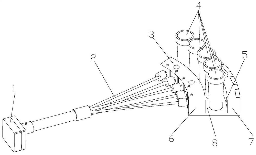
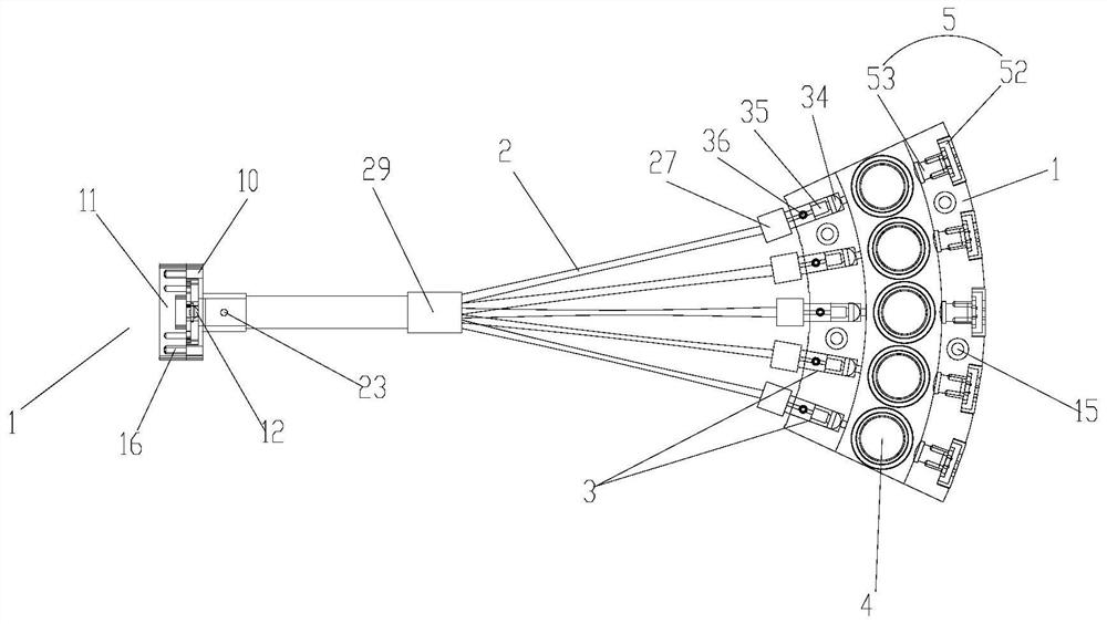
[0040] Such as Figure 1-2 As shown, this embodiment provides a blue light multi-thread concurrent detection device, including a light-emitting diode assembly 1, an optical fiber group, a blue light signal transmitter group 3, and a photoelectric signal receiver group; the optical fiber group includes a plurality of optical fibers 2, The blue light signal transmitter group 3 includes a plurality of blue light signal transmitters, and the photoelectric signal receiver group includes a plurality of photoelectric signal receivers 5; each of the two ends of the optical fiber 2 is respectively connected to the light emitting diode Between the component 1 and one of the blue light signal transmitters; the blue light multi-threaded concurrent detection device also includes a double-arc colorimetric lamp bracket, and the double-arc colorimetric lamp bracket includes a set for placing a plurality of blue light signals The inner arc-shaped shell 6 of the transmitter and the outer arc-sh...
Embodiment 2
[0043] Such as Figure 1-2 As shown, the blue light multi-thread concurrent detection device includes multiple groups of photoelectric signal receivers 5 arranged with the same diameter, the arc groove detection bit and the blue light signal transmitter. By arranging the photoelectric signal receiver 5, the detection position of the arc-shaped groove and the blue light signal transmitter with the same diameter, the light extraction efficiency and stability can be improved.
Embodiment 3
[0045] Such as Figure 1-2 As shown, the light-emitting diode assembly 1 includes an LED circuit board installation lower block 10, an LED circuit board installation upper block 11, an LED lamp 12 and a control circuit board; the LED lamp 12 and the control circuit board are arranged on the LED The circuit board installation lower block 10 is connected to the installation box body formed by the LED circuit board installation upper block 11; the control circuit board is provided with a microprocessor to control the LED lamp 12 to emit light; the LED circuit board is installed under the One side of the block 10 is provided with a circular hole for connecting the optical fiber group. In this embodiment, the lower block 10 installed on the LED circuit board and the upper block 11 installed on the LED circuit board form an installation box body for accommodating the LED lamp 12, which is convenient for installation and disassembly, and the optical fiber group is connected through a...
PUM
 Abstract
Description
Claims
Application Information