Miniature gas chromatographic column capable of using air as carrier gas and manufacturing method thereof

A technology of micro gas chromatography and production method, which is applied in the separation of complex multi-component organic compound gas, high reliability micro gas chromatography column, and high resolution field, which can solve the problem of increasing the coating area of ​​stationary phase, poor stability, and insufficient separation performance and other problems, to achieve the effect of increasing the coating surface area, increasing the roughness of the inner wall, and better thermal stability

Active Publication Date: 2021-10-01
XI AN JIAOTONG UNIV
View PDF11 Cites 1 Cited by
  • Summary
  • Abstract
  • Description
  • Claims
  • Application Information

AI Technical Summary

Problems solved by technology

[0005] Aiming at the problems of insufficient separation performance, poor stability and the need for high-purity carrier gas in the current microchromatography technology, the present invention aims to invent a micro-chromatographic column with high stability and high column efficiency, which uses air as the carrier gas (no need to carry additional carrier gas cylinders) , the stationary phase support on the inner surface of the chromatographic column provides a rough surface, and its mesoporous structure greatly increases the coating area of ​​the stationary phase, improving the separation ability within the limited length of the chromatographic column

Method used


Image

  • Miniature gas chromatographic column capable of using air as carrier gas and manufacturing method thereof
  • Miniature gas chromatographic column capable of using air as carrier gas and manufacturing method thereof
  • Miniature gas chromatographic column capable of using air as carrier gas and manufacturing method thereof

Examples


Embodiment 1

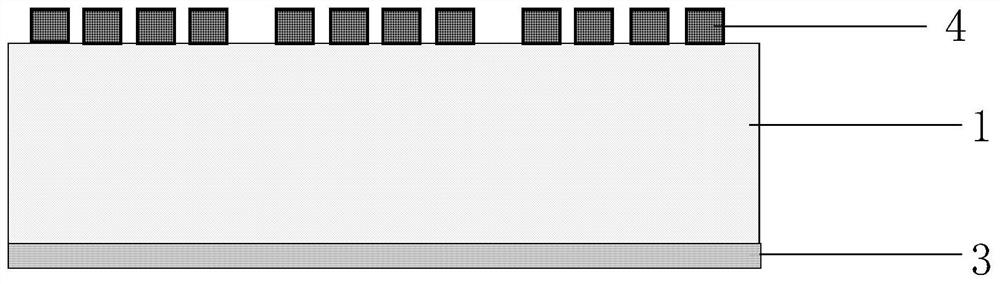
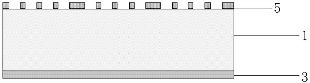
[0074] Step 1) Perform photolithography on a 4-inch 500nm thick N-type double-sided polished and single-sided oxidized silicon wafer 1, and form a 160nm thick aluminum mask layer 5 by electron beam evaporation and stripping.

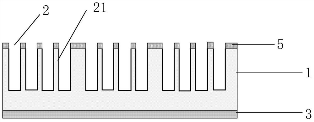
[0075] In step 2), using aluminum as a mask, the chromatographic column microchannel 2 is formed by a deep reactive ion etching method. The size of the microchannel of the chromatographic column is: total length 3m; width 200um; depth 250um; microcolumn arrays are regularly arranged in the microchannel of the chromatographic column, the column cross section is circular, the diameter is 30um, and the spacing on the flow velocity section is 26um. The distance from the wall in the direction of vertical flow velocity is 29um.

[0076] Step 3), use concentrated sulfuric acid with a mass ratio of 60°C: water: nitric acid = 16:4:1 mixed solution and a mixed solution with a mass ratio of concentrated sulfuric acid: hydrogen peroxide = 3:1 to soak and clean the m...

Embodiment 2

[0096] Step 1) Perform photolithography on a 4-inch 600nm thick N-type double-sided polished and single-sided oxidized silicon wafer 1, electron beam evaporation and stripping to form an aluminum mask layer 5 with a thickness of 150nm.

[0097] In step 2), using aluminum as a mask, the chromatographic column microchannel 2 is formed by a deep reactive ion etching method. The size of the column microchannel is as follows: the total length is 1m; the width is 200um; the depth is 100um; the microcolumn array is regularly arranged in the column microchannel, the cross section of the column is square, the side length is 30um, and the spacing on the flow velocity section is 25um, 30um away from the wall in the direction of vertical flow velocity.

[0098] Step 3), use concentrated sulfuric acid with a mass ratio of 60°C: water: nitric acid = 16:4:1 mixed solution and a mixed solution with a mass ratio of concentrated sulfuric acid: hydrogen peroxide = 3:1 to soak and clean the micro...

Embodiment 3

[0117] Step 1) Perform photolithography on a 4-inch 800nm ​​thick N-type double-sided polished and single-sided oxidized silicon wafer 1, and form a 170nm aluminum mask layer 5 by electron beam evaporation and stripping.

[0118] In step 2), using aluminum as a mask, the chromatographic column microchannel 2 is formed by a deep reactive ion etching method. The size of the microchannel of the chromatographic column is: total length 3m; width 200um; depth 300um; microcolumn arrays are regularly arranged in the microchannel of the chromatographic column, the cross section of the column is circular, the diameter is 30um, and the spacing on the flow velocity section is 25um , 30um away from the wall in the direction of vertical flow velocity.

[0119] Step 3), use concentrated sulfuric acid with a mass ratio of 60°C: water: nitric acid = 16:4:1 mixed solution and a mixed solution with a mass ratio of concentrated sulfuric acid: hydrogen peroxide = 3:1 to soak and clean the microcha...


PUM

PropertyMeasurementUnit
concentrationaaaaaaaaaa
thicknessaaaaaaaaaa
thicknessaaaaaaaaaa

Abstract

The invention discloses a miniature gas chromatographic column capable of using air as carrier gas and a manufacturing method thereof. The manufacturing method comprises the following steps of photoetching and stripping on a silicon wafer to form an aluminum mask layer, forming a chromatographic column micro-channel with a micro-upright column array through etching, soaking the silicon wafer in an acid solution, removing the mask and bonding the silicon wafer with borosilicate glass, sputtering titanium and platinum on the back surface of the silicon wafer as a temperature measuring resistor, a heating wire and an electrode, sputtering gold as an electrode pin, enabling the capillary tube to be connected with two ports of the micro gas chromatographic column, and constructing mesoporous silica microspheres in a chromatographic column micro-channel, and coating an ionic liquid stationary phase in a static coating mode. The mesoporous structure in the chromatographic column greatly increases the coating area of a stationary phase, improves the separation capacity within the limited chromatographic column length, has good tolerance to oxygen, ensures high reliability, high stability and high column efficiency of the micro-chromatographic column in a high-temperature aerobic environment, can directly use air as carrier gas, and an excellent micro-chromatographic column is provided for a VOCs detection system.

Description

technical field [0001] The invention relates to the field of chromatographic analysis technology and the field of microelectromechanical systems, in particular to a high-separation, high-reliability micro-gas chromatographic column that can use air as a carrier gas and its manufacturing method. The invention is suitable for complex multi-component organic compound gases The separation can be applied to on-site respiratory diagnosis, environmental monitoring, etc. Background technique [0002] Gas chromatography is an efficient method for separating and detecting mixtures. The chromatographic columns used in traditional gas chromatography technology are packed columns or fused silica capillary columns, which have long column length, large volume, and long separation time. Therefore, the chromatographic system also has the problems of large volume, slow analysis, and high power consumption. It is applied to the analysis of on-site tests such as respiratory diagnosis and envir...

Claims


Application Information

Patent Timeline
Patent Type & Authority Applications(China)
IPC IPC(8): G01N30/60B01D15/10B01D53/04B01J20/283B01J20/30
CPCG01N30/6095G01N30/606B01D15/10B01J20/283B01D53/04B01D2257/708
Inventor 王海容石路嘉王久洪吴欣雨韩宝庆王大祚陈家洛
Owner XI AN JIAOTONG UNIV
Why Eureka
Try Eureka