Micro-fluidic chip based on electrohydrodynamics and micro sample application device and method

A microfluidic chip, kinetic technology, applied in chemical instruments and methods, measuring tubes/pipettes, laboratory containers, etc. Safe and easy to operate, easy to operate and safe, accurate effect of fixing effect

Active Publication Date: 2021-10-22
QINGDAO INST OF BIOENERGY & BIOPROCESS TECH CHINESE ACADEMY OF SCI
View PDF10 Cites 3 Cited by
  • Summary
  • Abstract
  • Description
  • Claims
  • Application Information

AI Technical Summary

Problems solved by technology

[0005] Electrohydrodynamic jet printing technology was originally applied in the field of materials, after development, the current electrohydrodynamic jet printing technology has also been applied in the field of biology Microfluidic chips are partially coupled, but at present, this technology generally requires sophisticated support and alignment equipment, precise size printing nozzles, and cumbersome conductive electrodes, so complex and sophisticated equipment is required to support this technology, so most of laboratories do not have the basis for this research

Method used


Image

  • Micro-fluidic chip based on electrohydrodynamics and micro sample application device and method
  • Micro-fluidic chip based on electrohydrodynamics and micro sample application device and method
  • Micro-fluidic chip based on electrohydrodynamics and micro sample application device and method

Examples


Embodiment 1

[0067] Preparation of microfluidic chip:

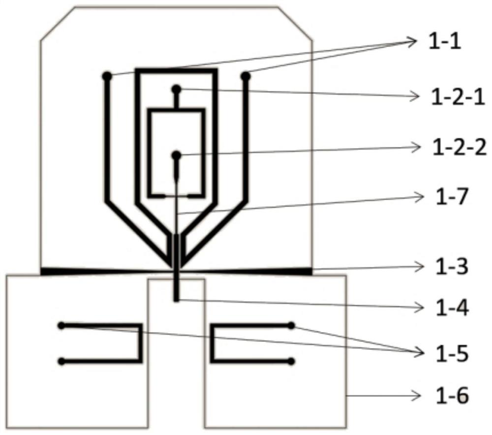
[0068] The prepared microfluidic chip structure is as follows figure 1 As shown, the chip is an integrated structure.

[0069] ①Design with CAD such as figure 1 The channel structure of the microfluidic chip shown, including microchannels 1-7, capillary embedded channels at the outlet of the microchannels, optical fiber channels 1-3, and electrode channels, is printed with a film mask. Drop the SU-8 photoresist on the cleaned silicon wafer to shake the glue, the thickness is about 120um. Finally, it is covered with a mask, exposed under an exposure machine, and the uncured part is cleaned with a developing solution to obtain a silicon wafer template.

[0070] ②Mix PDMS monomer and curing agent in a certain proportion to obtain PDMS polymer. Pour the PDMS polymer on the silicon wafer template with a thickness of about 1-10 mm, and obtain a PDMS chip with a channel structure after drying.

[0071] ③ On the PDMS chip with a channel ...

Embodiment 2

[0077] A microbial spotting device based on electrohydrodynamics, such as Figure 4 As shown, it includes: a microfluidic chip 1, the microfluidic chip has at least two sample inlets, and is provided with two opposite optical fiber channels;

[0078] Laser transmitter 2, which emits visible light band laser;

[0079] A laser detector 3 is used to detect an optical signal and convert the optical signal into an electrical signal; the laser detector includes but is not limited to a photodiode or a photomultiplier tube;

[0080] Two optical fibers, the optical fibers are embedded in the fiber channel, one of which is connected to the laser transmitter, and the other is connected to the laser detector;

[0081] The relay 5 is used to control the switch of the circuit;

[0082] A high-voltage DC power supply 6, the two poles of the high-voltage DC power supply are respectively connected to the upper electrode and the lower electrode of the microfluidic chip;

[0083] The data acq...

Embodiment 3

[0087] Taking the microfluidic chip applied to the coupling interface of flow sorting and mass spectrometry after microbiome droplet culture as an example, the chip structure is based on the chip structure prepared in Example 1 ( figure 1 ) as an example:

[0088] 1. Liquid culture and amplification of microorganisms in droplets

[0089] Use the common microfluidic cross-shaped droplet generation chip to generate droplets from the selection medium containing microorganisms. The droplet size is 10um-100um, preferably 80um. Microorganisms proliferate and fill the droplets.

[0090] 2. Label-free growth phenotype droplet sorting based on scattered light

[0091] Cultured droplets can be sorted using a label-free outgrowth phenotype droplet sorting system based on scattered light. Droplets overgrown with target microorganisms can be sorted and collected into one-milliliter centrifuge tubes.

[0092] 3. Separation of individual droplets

[0093] The microfluidic chip printed by...


PUM

PropertyMeasurementUnit
thicknessaaaaaaaaaa
lengthaaaaaaaaaa

Abstract

The invention provides a micro-fluidic chip based on electrohydrodynamics, a micro sample application device and a micro sample application method. The chip comprises: at least one capillary tube having an inlet end and an outlet end; a chip body, which comprises at least one sample inlet, and a micro-channel connected with the sample inlet and a capillary tube embedding channel connected with the micro-channel, wherein the capillary tube embedding channel is provided with an outlet end, the capillary tube is arranged in the capillary tube embedding channel and connected with the micro-channel, and the length of the capillary tube is larger than that of the capillary tube embedding channel; an upper electrode which is positioned on the chip body and is close to the capillary tube; and a lower electrode which is provided with an insulating support body, and the lower electrode is positioned below the outlet of the capillary tube. According to the chip, the capillary tube is embedded into the micro-fluidic chip, so that an accurate fixing effect is achieved, the structure is simplified, and full-automatic loading of a sample can be realized.

Description

technical field [0001] The invention belongs to the field of microfluidic chips, and in particular relates to a microfluidic chip based on electrohydrodynamics, a micro-volume spotting device and a method. Background technique [0002] Droplet generation technology is an important branch of microfluidic chip technology. Droplet-based microfluidic chip technology is compatible with numerous chemical and biological reagents and "electronic control", and has good programmability and constructability. The microfluidic chip droplet generation platform enables precise control and rapid mixing of samples in droplets, thereby reducing reaction time. Since microfluidic chip droplet technology can precisely control the generation and manipulation of droplets, and produce uniform monodisperse droplets, it has become a high-throughput platform for biomedical and chemical research. The generated droplet size is nL and pL level, which can be used as a reactor to directly synthesize part...

Claims


Application Information

Patent Timeline
Patent Type & Authority Applications(China)
IPC IPC(8): B01L3/00B01L3/02
CPCB01L3/0241B01L3/5027B01L3/00B01L3/02G01N21/65
Inventor 马波刁志钿葛安乐徐健
Owner QINGDAO INST OF BIOENERGY & BIOPROCESS TECH CHINESE ACADEMY OF SCI
Why Eureka
Try Eureka