Structure for improving mode separation ratio of Fabry-Perot MEMS acceleration sensitive chip

A Fabry Perot, sensitive chip technology, applied in the structural field of improving the modal separation ratio of Fabry Perot MEMS acceleration sensitive chips, can solve the problem of unfavorable cross-axis sensitivity suppression and improvement of modal separation ratio, process Complicated, unable to complete etching at the same time, etc., to achieve the effect of suppressing cross-sensitivity, improving the mode separation ratio, and solving the mutual interference of modes

Pending Publication Date: 2022-04-29
XI AN JIAOTONG UNIV
View PDF5 Cites 0 Cited by
  • Summary
  • Abstract
  • Description
  • Claims
  • Application Information

AI Technical Summary

Problems solved by technology

[0006] Chinese Patent No. 202011594186.X applied a double-layer S-shaped meandering cantilever beam sensitive structure that can solve the cross-axis crosstalk of the accelerometer in the implementation process of the integrated optomechanical accelerometer based on the hemispherical FP cavity chip. The customized seven-layer SOI substrate is superimposed, and the mode separation ratio can reach 12, but the process is more complicated, and the upper and lower springs must be misaligned due to the etching masking problem of the double-layer S-shaped cantilever beam structure. arrangement, otherwise the etching of the upper and lower layers of the spring-mass structure cannot be completed at the same time, which is not conducive to the suppression of the cross-axis sensitivity of the acceleration-sensitive structure and the improvement of the mode separation ratio

Method used


Image

  • Structure for improving mode separation ratio of Fabry-Perot MEMS acceleration sensitive chip
  • Structure for improving mode separation ratio of Fabry-Perot MEMS acceleration sensitive chip
  • Structure for improving mode separation ratio of Fabry-Perot MEMS acceleration sensitive chip

Examples


Embodiment Construction

[0034] The present invention will be further described in detail below in conjunction with specific embodiments, which are explanations of the present invention rather than limitations.

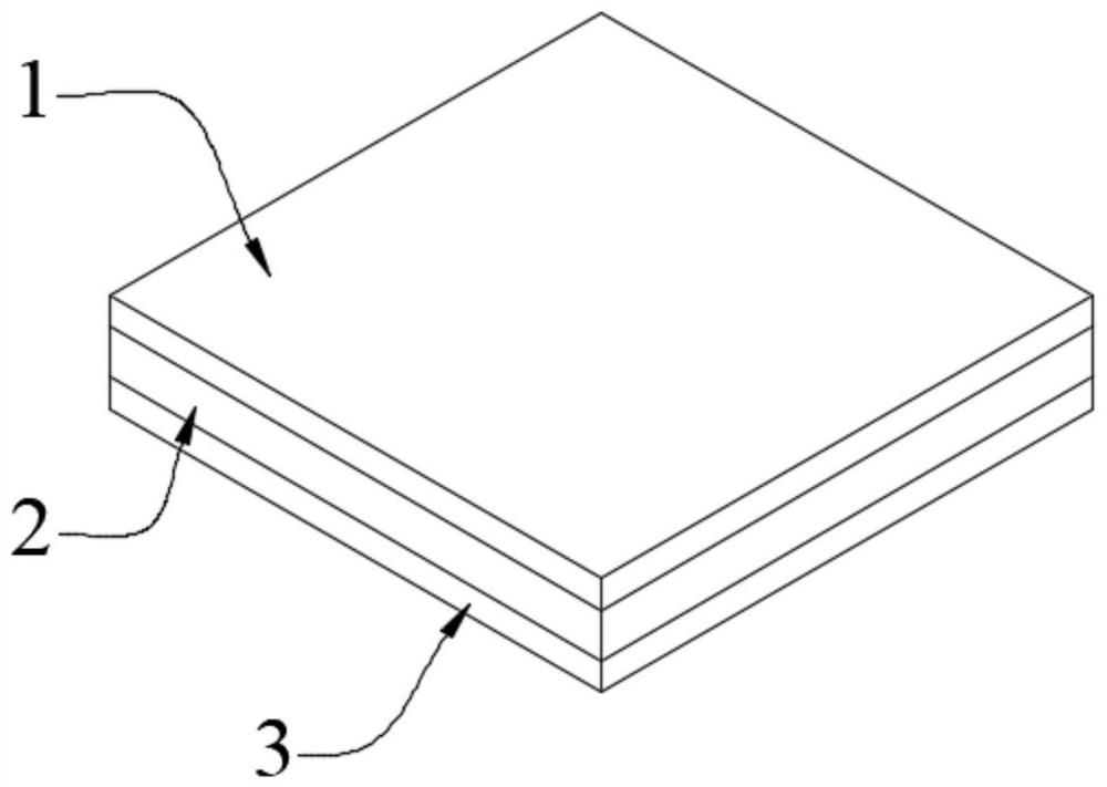
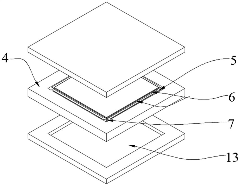
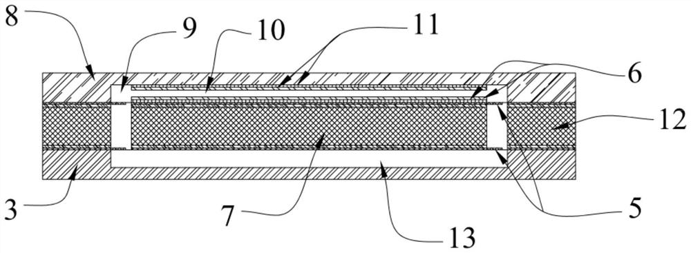
[0035] With the rapid development of micro-nano manufacturing technology and the expansion of market demand, MEMS acceleration sensors are gradually replacing traditional acceleration sensors. The Fabry-Perot optical MEMS acceleration sensor integrates a Fabry-Perot cavity and a MEMS spring-mass structure 12, and introduces optical detection technology into acceleration measurement. It has the advantages of high sensitivity, detection accuracy, and anti-electromagnetic interference.

[0036]Under the existing micro-manufacturing level, how to provide a Fabry-Perot optical MEMS acceleration sensitive chip with high separation ratio of out-of-plane rotation mode and out-of-plane vibration mode, and solve the problem of modal interaction in the measurement process. The problem of interference an...


PUM


Abstract

The invention relates to the technical field of micro electro mechanical systems, in particular to a structure for improving the modal separation ratio of a Fabry-Perot MEMS acceleration sensitive chip, which comprises a fixed mirror surface, a movable mirror surface and a supporting seat, and is characterized in that the movable mirror surface comprises an MEMS spring mass structure and a second optical film; the MEMS spring mass structure comprises a double-layer supporting beam structure, an MEMS mass block and a fixed frame, and the double-layer supporting beam structure is arranged in a full symmetry mode; and the second optical thin film is arranged on the MEMS mass block. According to the invention, the ratio of the out-of-plane torsion mode frequency to the out-of-plane vibration mode frequency of the chip can be obviously improved, and the cross sensitivity caused by the out-of-plane torsion of the MEMS mass block under the action of an acceleration signal in the non-sensitive axis direction and the influence on the sensitivity and the range of the sensor can be obviously inhibited; the parallelism of the fixed mirror surface and the movable mirror surface of the Fabry-Perot cavity is ensured, and the problem of mutual interference of modes in the measurement process is also solved.

Description

technical field [0001] The invention relates to the technical field of micro-electro-mechanical systems, in particular to a structure for improving the modal separation ratio of a Fabry-Perot MEMS acceleration-sensitive chip. Background technique [0002] Acceleration sensors can measure acceleration, speed, and position, and are key components in automotive safety, earthquake detection, inertial navigation, and other application fields. In recent years, due to the rapid development of micro-nano manufacturing technology and its inherent advantages such as mass production, low price, and high yield, MEMS acceleration sensors with advantages such as high precision, small size, and low power consumption are gradually occupying the traditional The market for acceleration sensors has become a large category of acceleration sensors. With the further improvement of people's performance requirements for MEMS acceleration sensors, people have integrated optical detection technology...

Claims


Application Information

Patent Timeline
IPC IPC(8): G01P15/093B81B7/02
CPCG01P15/093B81B7/02
Inventor 韦学勇李博赵明辉齐永宏蒋庄德
Owner XI AN JIAOTONG UNIV
Why Eureka
Try Eureka