High-efficiency on-chip acousto-optic deflector and preparation method thereof
An acousto-optic deflector, high-efficiency technology, applied in microlithography exposure equipment, instruments, optics, etc., can solve the problems of large coupling area size of acousto-optic deflector, insufficient utilization of acoustic wave energy, etc., to achieve the solution of acoustic energy utilization Insufficient efficiency, improved acousto-optic interaction, and solved the effect of excessive size of the coupling region
- Summary
- Abstract
- Description
- Claims
- Application Information
AI Technical Summary
Problems solved by technology
Method used
Image
Examples
Embodiment 1
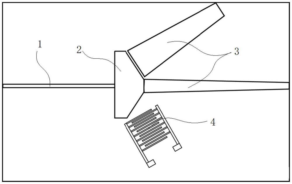
[0035] like figure 1 As shown, a high-efficiency on-chip acousto-optic deflector includes a lithium niobate-silicon nitride heterostructure disposed on a silicon oxide substrate; the lithium niobate-silicon nitride heterostructure includes a lithium niobate film and a photonic multi-mode coupler 2 formed with a silicon nitride structure integrated on the lithium niobate film; the lithium niobate film is provided with an excitable acoustic wave interdigital transducer 4, and the interdigital transducer 4 includes Several interdigitated electrodes. The invention comprehensively utilizes the excellent piezoelectric properties of the lithium niobate film and the diffraction effect of the acoustic grating, and places the interdigital transducer 4 on the side of the photonic waveguide coupler to realize the high-efficiency deflection effect of the surface acoustic wave on the photons. The invention uses the coupler structure to reduce the structure size of the existing acousto-opti...
Embodiment 2
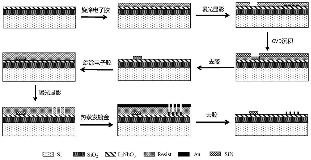
[0044] The present embodiment provides a method for preparing a high-efficiency on-chip acousto-optic deflector, comprising the following steps:
[0045] S1. On the substrate covered with the lithium niobate film, a silicon nitride film with a thickness of 200 nm is deposited by chemical vapor deposition;
[0046] S2. Using electron beam direct writing system (EBL, Vistec EBPG 5000+) to expose positivity electron paste (APR6200) on the pre-prepared silicon nitride film; the thickness is about 400nm, and then bake on a hot plate at 130°C After baking for 5 minutes, the required waveguide and coupler patterns can be obtained on the electronic glue after developing with xylene;
[0047] S3. Using reactive ion etching equipment, using the pattern obtained on the electronic glue as a mask, dry etching is performed, and the sidewall morphology is required to be smooth and steep; the etching parameters are set at any time according to the etching effect of the equipment;
[0048] S4...
Embodiment 3
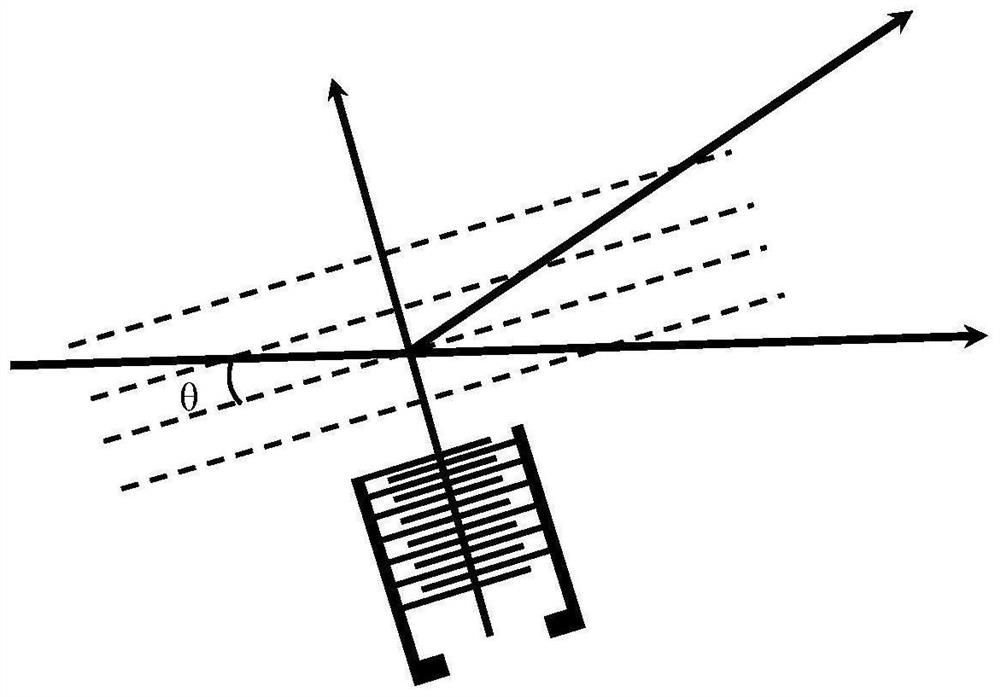
[0053] As shown in the figure, it is a schematic diagram of the corresponding test system of the present invention. The test system mainly includes: a tunable laser, an optical fiber, a polarization controller, a photodetector, a vector network analyzer, and a spectrometer.
[0054] During device testing, the process of converting microwaves to surface acoustic waves is based on the inverse piezoelectric coupling effect of lithium niobate films. The interdigital transducer 4 converts the input microwave electrical signal into the surface acoustic wave signal of the lithium niobate film, so that the lithium niobate film has periodic mechanical strain field distribution, forming an equivalent Bragg grating, when the light wave in the optical waveguide After passing through the structure of periodic strain distribution, the direction will be deflected. The photons in the deflected direction will be output through the waveguide on the upper side, and the output optical signal will...
PUM
| Property | Measurement | Unit |
|---|---|---|
| Thickness | aaaaa | aaaaa |
| Thickness | aaaaa | aaaaa |
| Width | aaaaa | aaaaa |
Abstract
Description
Claims
Application Information
 - R&D
- Intellectual Property
- Life Sciences
- Materials
- Tech Scout
- Unparalleled Data Quality
- Higher Quality Content
- 60% Fewer Hallucinations
Browse by: Latest US Patents, China's latest patents, Technical Efficacy Thesaurus, Application Domain, Technology Topic, Popular Technical Reports.
© 2025 PatSnap. All rights reserved.Legal|Privacy policy|Modern Slavery Act Transparency Statement|Sitemap|About US| Contact US: help@patsnap.com


