Method and apparatus for manufacturing a rare-earth metal doped optical fiber preform

A preform and equipment technology, applied in glass manufacturing equipment, light guides, manufacturing tools, etc., can solve problems such as difficult doping of rare earth dopants, achieve high pump power absorption, low core attenuation rate, numerical aperture small effect

Inactive Publication Date: 2001-08-08
JDS单相公司
View PDF16 Cites 90 Cited by
  • Summary
  • Abstract
  • Description
  • Claims
  • Application Information

AI Technical Summary

Problems solved by technology

Nevertheless, in current practice, it is difficult to dope high concentrations of rare earth dopants, especially the commonly used rare earth element neodymium (Nd) with limited total doping levels.
[0010] Issues include: The most common method of pre

Method used


Image

  • Method and apparatus for manufacturing a rare-earth metal doped optical fiber preform
  • Method and apparatus for manufacturing a rare-earth metal doped optical fiber preform
  • Method and apparatus for manufacturing a rare-earth metal doped optical fiber preform

Examples


Embodiment 1

[0096] An optical fiber preform was prepared using the basic glass deposition components and parameters in Table 1.

[0097] cladding formation

(1450℃ hot zone, 3 passes)

core formation

(1450℃ hot zone, 4 passes)

components

flow

components

flow

SiCl 4

500cc / 20℃, 1.1g / min

SiCl 4

200cc / 22℃, 0.66g / min

GeCl 4

25cc / 20℃, 0.03g / min

POCl 3

687cc / 20℃, 0.16g / min

POCl 3

30cc / 20℃, 0.007g / min

SF 6

0.8cc / min

SF 6

0.25cc / min

O 2

1,000cc / min

O 2

1,000cc / min

he

1,000cc / min

he

1,000cc / min

[0098] * Sintered at 1960°C

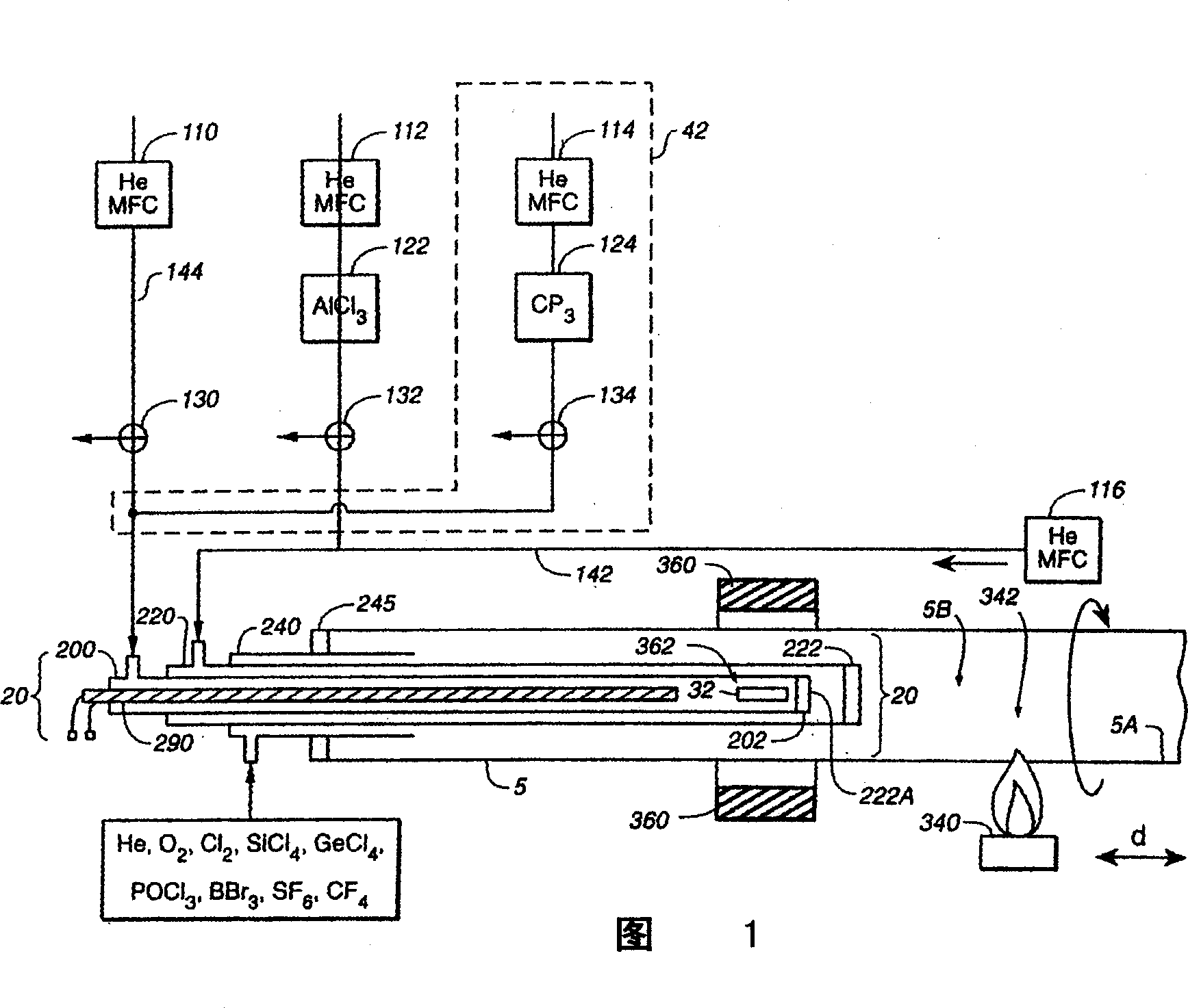
[0099] More specifically, during the deposition process, a stream of glass-forming component vapor containing the above-mentioned components is introduced into the cavity of the quartz tube 5 through the outer delivery tube 240 of the multiple concentric delivery system 20 of FIG. 1, and reacts to form a powd...

Embodiment 1A-1C

[0103] Three kinds of optical fiber preforms (Examples 1A-1C) were prepared by the method of Example 1. However, the ytterbium chloride in Example 1A vaporizes at 930°C, in Example 1B at 950°C, and in Example 1C at 980°C. It is observed that the core depositions of Examples 1A-1C are the same, but the content of ytterbium oxide increases from 1A to 1C, that is, increases with the increase of gasification temperature. The concentration of ytterbium oxide in Example 1C exceeds 3 wt%. Example 1D

Embodiment 1D

[0104] An optical fiber preform was prepared by the method of Example 1. However, in this embodiment, the core layer is formed not by 4 passes but by 8 passes. The core composition of the obtained optical fiber preform is similar to that of the preform of Example 1, but the core diameter is larger, so it is more suitable for drawing multimode optical fiber. Example 1E


PUM


Abstract

A method and apparatus is disclosed for the manufacture of an optical fiber preform having incorporated therein a comparatively high concentration of rare earth metal dopant material, and which thus can be drawn and processed into an optical fiber having low numerical aperture, low core attenuation, and high pumping power absorption. The high concentrations of rare earth metal dopant material are accomplished through a ''hybrid vapor processing'' (HVP) method or a ''hybrid liquid processing'' (HLP) method, either being practiced in combination or independently of one another. The HVP method involves the vaporization of a rare earth metal halide by the exposure thereof to a sufficiently elevated temperature, independently, or contemporaneously with the transport of the resultant rare earth metal halide laden vapor, into a glass-forming oxidation reaction zone on a flowing stream of essentially an unreactive inert gas, such as helium. According to the HLP method, a first amount of rare earth metal dopant is provided according to the HVP method and/or other vapor source of rare earth metal dopant which is mixed with glass-forming vapors to form a deposited soot layer on the internal surface of a glass tube. The soot-deposited tube is then impregnated with a dopant solution comprising, a second amount of rare earth metal dopant. The tube is then thermally collapsed resulting in an optical preform with an enhanced amount of rare earth metal dopant incorporated at a comparatively high concentration. The apparatus comprises means, such as tubes, for introducing the rare earth metal dopant as a vapor, formed from a solid state form of the dopant, into the main glass deposition tube separately from glass-forming material vapors and oxygen for the reaction within the main tube.

Description

[0001] related application [0002] This application claims priority to provisional application 60 / 091,290, filed June 30, 1998, and provisional application 60 / 091,154, filed June 30, 1998. field of invention [0003] The present invention relates to a method of making an optical fiber preform doped with a predetermined high level of rare earth dopant, in particular wherein the concentration of the rare earth dopant is relatively high and the cross-sectional geometry of the preform promotes good mode disturbance. Background of the invention [0004] Optical fiber is an ultra-thin light guide. Light is drawn into one end, travels forward through the fiber, whether the fiber is curved or straight, and finally exits the other end. By pumping light into fibers in a predetermined manner, large amounts of information can be communicated almost instantaneously (ie, at the speed of light) over large bandwidths across vast geographic distances. Because it is thin, fast and strong, ...

Claims


Application Information

Patent Timeline
IPC IPC(8): G02B6/00C03B37/018C03B37/027C03C25/10C03C25/105
CPCC03B37/01807C03B37/027C03B37/01838C03C25/105C03B2201/36C03B2201/34C03B2207/90
Inventor 张英华B·M·拉利伯坦R·F·鲁滨逊
Owner JDS单相公司
Why Eureka
Try Eureka