Supercharge Your Innovation With Domain-Expert AI Agents!

Laser modulation driving circuit having self-regulating constant current source

A driving circuit, constant current source technology, applied in lasers, laser parts, semiconductor lasers, etc., can solve problems such as deviation from ideal design values, output voltage amplitude changes, and yield decline.

Inactive Publication Date: 2004-01-14
INST OF MICROELECTRONICS CHINESE ACAD OF SCI
View PDF0 Cites 1 Cited by
  • Summary
  • Abstract
  • Description
  • Claims
  • Application Information

AI Technical Summary

Problems solved by technology

[0004] In the actual manufacturing of laser drive circuit chips, due to deviations in device processing such as ion implantation, epitaxy, and gate groove corrosion, the leakage current or / and load resistance under zero gate bias deviate from the ideal design value, resulting in output The voltage amplitude changes greatly, resulting in a decline in yield

Method used


Image

  • Laser modulation driving circuit having self-regulating constant current source
  • Laser modulation driving circuit having self-regulating constant current source
  • Laser modulation driving circuit having self-regulating constant current source

Examples


Embodiment Construction

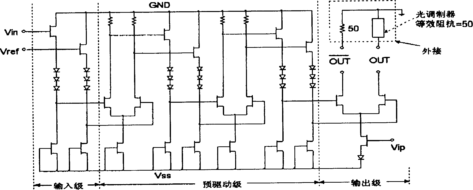
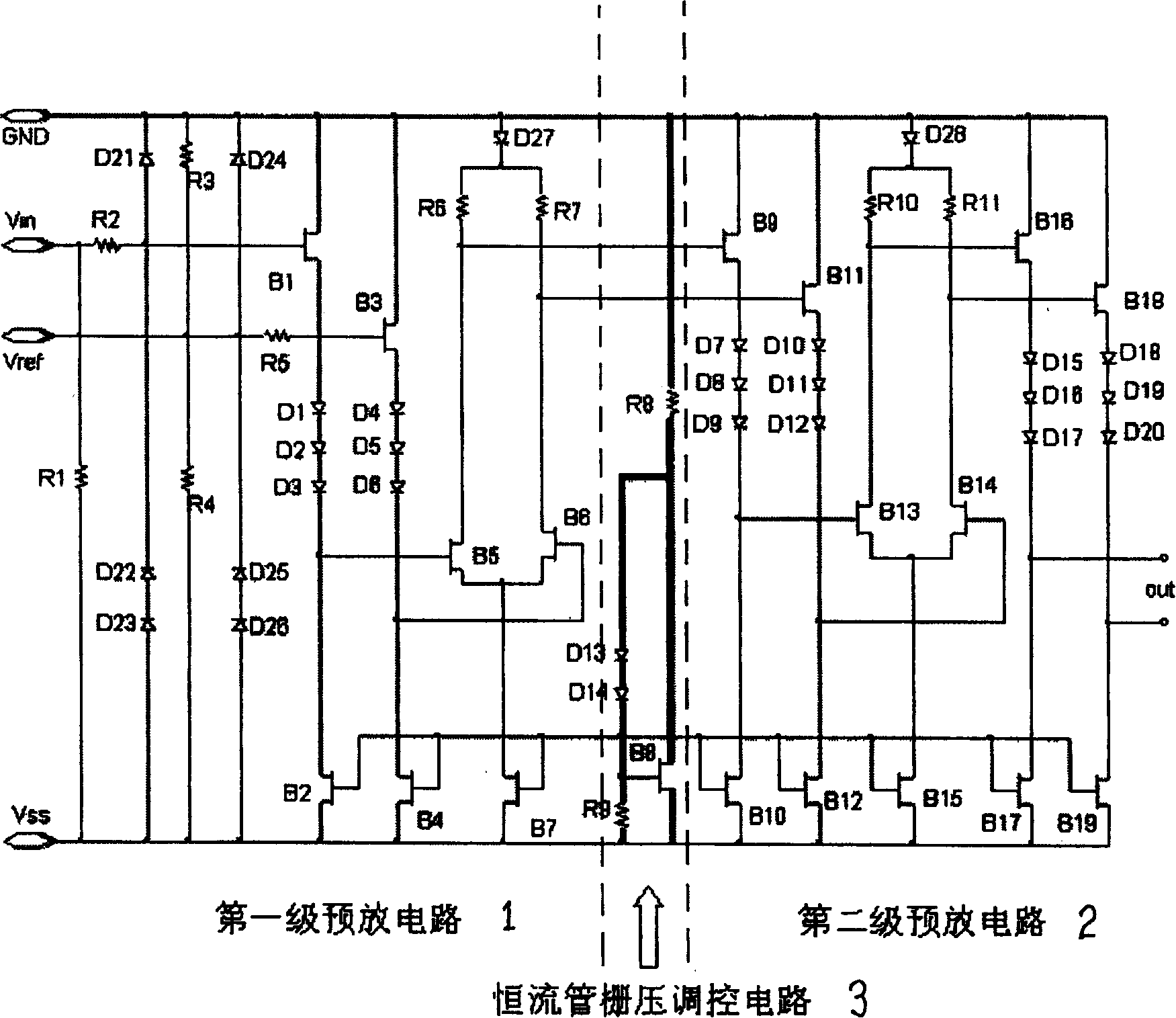
[0022] see figure 2 , the circuit with self-adjusting constant current source of the present invention is as follows figure 2 shown. The main difference between the present invention and the prior art is that the gate sources of all constant current source transistors in the prior art are short-circuited, and the drain current when the gate is zero-biased is used as the constant current current of the differential pair; the present invention The gate of the constant current tube is not directly connected to the source, but the drain current of the constant current tube is controlled by the gate voltage provided by another additional constant current tube gate voltage regulation circuit 3 as the constant current of the differential pair. The laser modulation driving circuit with self-adjusting constant current source includes: a first-stage pre-amplifier circuit 1 (in the prior art), a second-stage pre-amplifier circuit 2 (in the prior art), a constant-current tube grid Vol...


PUM


Abstract

The invention provides a laser device modulation drive circuit with self-adjusting constant-current source comprising, a first pre-sparking circuit, a second pre-sparking circuit, a constant-current tube grid voltage regulation and control circuit connected between the first pre-sparking circuit and the second pre-sparking circuit and includes a field-effect-transistor, whose grid is in series connection with a diode and connects with the drain of the field-effect-transistor and to the ground via a resistance. By using the circuit of the present invention, the rise and fall resulted from the processing variance of the differential amplifier output voltage amplitude can be reduced, the processing latitude in the circuit chip manufacturing can also be improved, thus increasing the rate of finished products.

Description

technical field [0001] The present invention relates to the field of semiconductor technology, in particular to a laser modulation driving circuit with a self-adjusting constant current source. Background technique [0002] Laser modulation driving circuit is an important part of optical transmitter in optical fiber communication. Since it needs to operate at high speeds of several gigabits per second, the circuit usually consists of several stages of ECL-level source-coupled field-effect transistor logic (SCFL) differential amplifiers connected in series, and the output is required to reach 2.5-3 volts peak-to-peak Voltage (corresponding to 50-60mA signal output current). When using gallium arsenide (GaAs) material to make this kind of monolithic circuit, the process deviation of the threshold value of the constant current source device of the differential amplifier HEMT (or MESFET) and the resistance value of the load resistor often lead to insufficient voltage amplitude ...

Claims


Application Information

Patent Timeline
IPC IPC(8): H01S5/00
Inventor 刘训春张龙海李无暇王润海罗明雄
Owner INST OF MICROELECTRONICS CHINESE ACAD OF SCI
Features
  • R&D
  • Intellectual Property
  • Life Sciences
  • Materials
  • Tech Scout
  • Unparalleled Data Quality
  • Higher Quality Content
  • 60% Fewer Hallucinations
Learn More