Technique for purifying and recovering argon gas by rare earth lanthanide series radical alloy degasser in single-crystal silicon preparation

A rare earth lanthanum and getter technology, applied in non-metallic elements, inert gas compounds, inorganic chemistry, etc., can solve the problems of complex process flow, high impurity content, high labor intensity of workers, etc., and achieve cost reduction and high absorption. In addition to efficiency, the effect of high practical value

Inactive Publication Date: 2007-07-04
天津环煜电子材料科技有限公司
View PDF0 Cites 8 Cited by
  • Summary
  • Abstract
  • Description
  • Claims
  • Application Information

AI Technical Summary

Problems solved by technology

(Rare Metals, Volume 12, Issue 5, 1988. Zhang Yiyan, "Selection of Argon Purification and Recovery Schemes in Silicon Single Crystal Plants") But this technology still has the following shortcomings: 1. Mixed rare earths are difficult to process, and the relatively large surface area affects the purification efficiency
2 Mixed rare earths are very active and easily oxidized in the air, making it difficult to preserve
It is easy to catch fire when filling, so it is not safe
3 Sponge titanium is only used as a filler to increase porosity, and the gas absorption efficiency is not high at 400 ° C. If the temperature is too high, the rare earth will be sintered
4Mixed rare earth and sponge titanium are semi-finished products, and the high impurity content may affect the quality of monocrystalline silicon
5 Silicon si

Method used


Image

  • Technique for purifying and recovering argon gas by rare earth lanthanide series radical alloy degasser in single-crystal silicon preparation
  • Technique for purifying and recovering argon gas by rare earth lanthanide series radical alloy degasser in single-crystal silicon preparation
  • Technique for purifying and recovering argon gas by rare earth lanthanide series radical alloy degasser in single-crystal silicon preparation

Examples


Embodiment 1

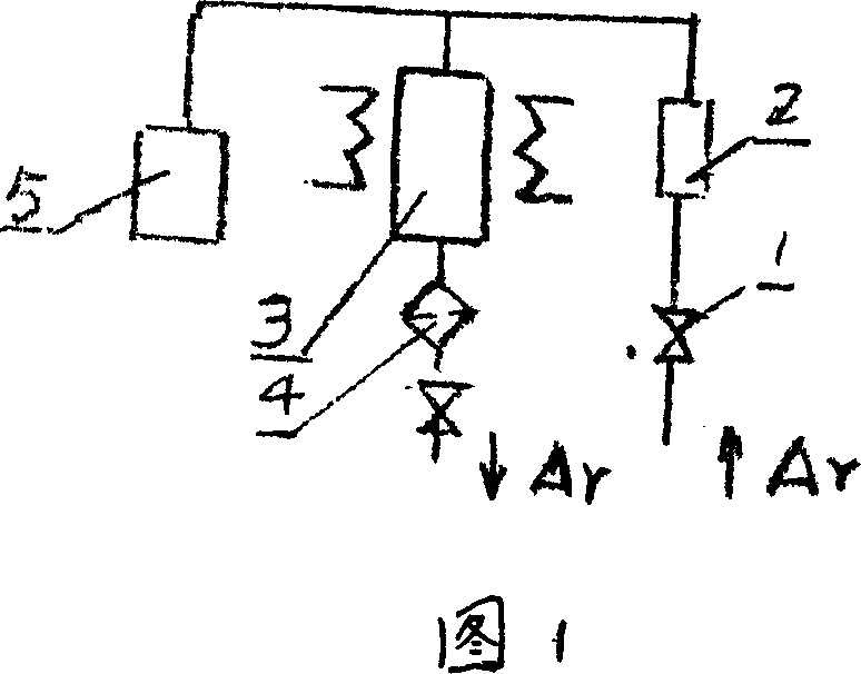
[0032] Combined with the process flow diagram 1: the non-high-purity argon gas entering the single crystal furnace is purified by the purification device (3) equipped with the above-mentioned getter to prepare high-purity argon (purity 99.999-99,9999%), and then micro The dust filter (4) removes dust (at this time, the dust content is no more than 3.5 pieces of 0.3 micron dust per liter) and then enters the single crystal furnace. The vacuum pump (5) is used to activate, ventilate and check for leaks of the CF01 agent, so as to ensure that the argon gas entering the single crystal furnace is high-purity and stable and has high economic benefits, and the process is simple and flexible.

[0033] During the preparation of single crystal silicon, volatiles are continuously produced in the single crystal furnace, and the volatiles must be taken out of the single crystal furnace by argon. Contaminated argon is discharged from the exhaust port of the single crystal furnace. For the ...

Embodiment 2

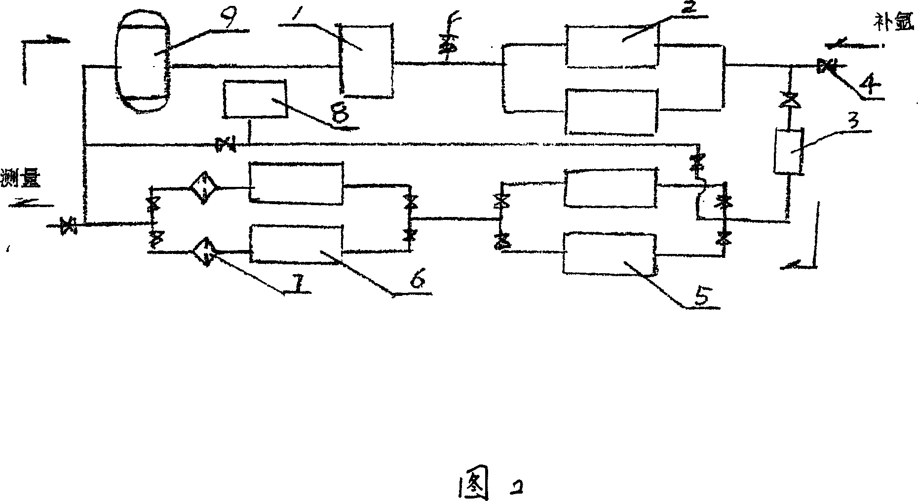
[0035] The method of using rare earth lanthanide-based alloy getters to purify and recycle argon gas in zone-melting single silicon crystals is shown in Figure 2 in conjunction with the process flow. Since there are very few volatile substances in the zone-melting single crystal furnace, the argon gas in the furnace is very low. The purity is relatively high, and the zone melting process is an atmospheric argon flow process, there is no large amount of oil mist generated by the vacuum pump to pump the single crystal furnace, so there is no need for degreasing treatment. The argon gas discharged from the single crystal furnace (1) is compressed by a membrane oil-free compressor (2) into a dryer (5) equipped with 4A molecular sieves for deep water removal. The other set is used to regenerate the 4A molecular sieve to ensure continuous operation. The regeneration process is as follows: After absorbing water at room temperature, the 4A molecular sieve has a strong water absorption...

Embodiment 3

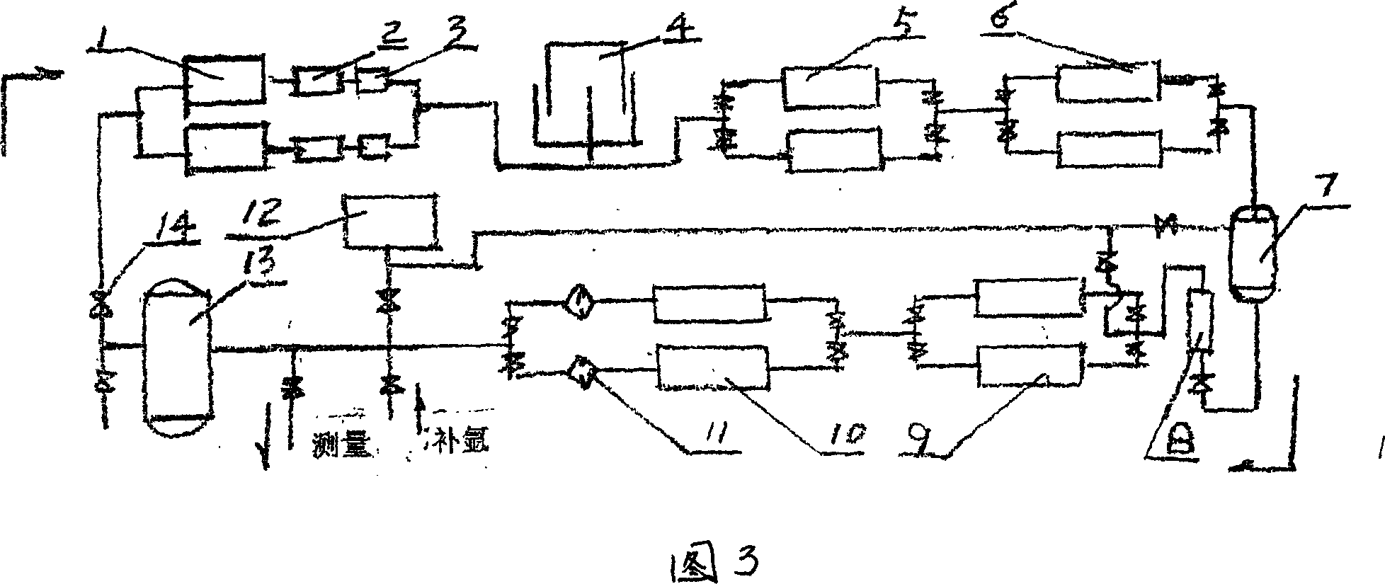
[0037] The method of using rare earth lanthanide-based alloy getters to purify and recycle argon gas in Czochralski single crystal silicon. The combined process flow is shown in Figure 3. Almost all Czochralski single crystal silicon adopts a negative pressure process. The single crystal furnace (1) system The argon gas discharged from the medium vacuum pump (2) contains a large amount of oil mist. After removing most of the oil mist through the small oil-gas separator (3), it enters the gas cabinet (4) sealed with low-volatile special oil. The function of the gas cabinet is Store argon and ensure that the outlet of the vacuum pump is at normal pressure. The oil-free film compressor (5) injects the argon gas in the gas tank into the medium-pressure tank (7), and the pressure of the argon gas has risen to 0.2-0.3 MPa at this time, so as to ensure that the argon gas can pass through the purification system at all levels. After passing through the dry oil absorber (9) and the CF0...


PUM


Abstract

The invention discloses a rare earth lanthanide base alloy getter (CF01 agent), comprising 65% of rare earth lanthanide and 35% metal element. Said rare earth lanthanide includes lanthanum, cerium, praseodymium and Neodymium; and said metal element concludes ferric, titanium, magnesium, copper and zinc. The invention also discloses a method for purifying argon gas with CF01 agent during high-purity argon gas preparation, which comprises following steps: (1) preparing high-purity argon gas through purifying cheap and non-high purity argon gas by using CF01 agent, and applying it into single-crystal silicon preparing process; (2) purifying and cyclic recovering argon gas from mono-crystal single-crystal silicon with CF01 agent; (3) purifying and cyclic recovering argon gas from czochralski single-crystal silicon with CF01 agent; (4) purifying and recovering (not cyclic) argon gas from mono-crystal and czochralski single-crystal silicon and preparing regenerative high-purity argon gas. The CF01 agent is characterized in that the comprehensive gettering performance and ratio of performance to price are better than that of current ones, and it can also recover argon gas discharged in single-crystal silicon preparation process, which can not only increase economic benefit, but also save energy and protect environment.

Description

technical field [0001] The invention relates to the purification and recovery of argon, more specifically, the preparation process of using a rare earth lanthanide-based alloy getter to purify argon and recover argon in the preparation of single crystal silicon. Background technique [0002] Argon is an inert gas and does not react chemically with any substance. Therefore, it is widely used in many industries of the national economy as protective gas, carrier gas, and dilution gas, such as electronics, metallurgy, chemical industry, physical and chemical analysis, light source, welding , Monocrystalline silicon preparation, etc. In the application, its inertness is mainly used, so the purity of argon is required to be as high as possible, and the impurities contained in it are as small as possible, so as not to lose the protective effect due to the reaction of impurities with the protected substance. Among them, single crystal silicon is the basic material of the electronic...

Claims


Application Information

Patent Timeline
IPC IPC(8): C01B23/00C22C28/00C22C30/00
Inventor 张忆延
Owner 天津环煜电子材料科技有限公司
Why Eureka
Try Eureka