
Lithium-iron-phosphorus-sulfur-carbon composite and method for producing same

a technology of lithium-iron phosphorus and carbon composite, which is applied in the direction of cell components, final product manufacturing, sustainable manufacturing/processing, etc., can solve the problems of increasing the chemical formula weight of the active material of the electrode, reducing the electrical conductivity of the electrode, and reducing the chemical formula weight of the active material. , to achieve the effect of high electrode utilization rate, high electrode utilization rate and high capacity

Active Publication Date: 2019-07-30
NAT INST OF ADVANCED IND SCI & TECH
View PDF18 Cites 0 Cited by
  • Summary
  • Abstract
  • Description
  • Claims
  • Application Information

AI Technical Summary

Benefits of technology

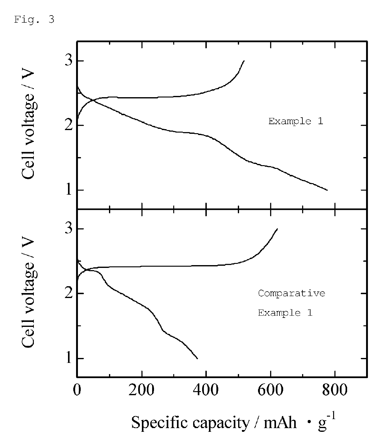
[0038]The composite according to the present invention (the lithium-iron-phosphorus-sulfur-carbon composite) refers to a submicron particle with a crystallite size of 80 nm or less, in particular 50 nm or less, and the composite has a stabilized metastable phase in which iron atoms and phosphorus atoms are incorporated inside the lithium sulfide crystal lattice, with carbon uniformly dispersed. In this composite according to the present invention, phosphorus atoms and iron atoms incorporated into the lithium sulfide crystal lattice bind to sulfur atoms to thereby enhance the electrical conductivity even inside the lattice. Therefore, the composite achieves a high electrode utilization rate (in particular, a cathode utilization rate) and sufficiently exhibits high-capacity characteristics inherent to lithium sulfide. In addition, the bonds between sulfur and phosphorus or iron in the composite of the present invention suppress the dissolution and flow of polysulfide occurring during the Li extraction and insertion reaction, contributing to excellent cycle characteristics. Moreover, the presence of iron and carbon enhances the electrical conductivity. Thus, the composite can serve as a high-capacity cathode active material.
[0039]As described above, the composite according to the present invention (the lithium-iron-phosphorus-sulfur-carbon composite) is a highly useful substance as an electrode active material (in particular, a cathode active material) for lithium-ion secondary batteries, such as non-aqueous electrolyte lithium-ion secondary batteries and all-solid-state lithium-ion secondary batteries.
[0040]The production method according to the present invention can produce the composite according to the present invention (the lithium-iron-phosphorus-sulfur-carbon composite), which has such excellent properties, in a relatively simple manner.

Problems solved by technology

However, elemental sulfur alone does not contain lithium, and lithium or a lithium-containing alloy is thus required for use in the anode, leaving few options for the anode.
However, lithium sulfide, as lithium polysulfide, dissolves into an organic electrolyte during charge or discharge in a battery system that contains the organic electrolyte, and migrates into the anode to cause segregation (e.g., NPL 1), making it difficult to extract the inherent high capacity of lithium sulfide.
However, adding a large amount of other elements increases the chemical formula weight of the electrode active material, and also reduces the relative Li content, decreasing the theoretical capacity.
However, decreases in the amount of other elements increase free sulfur, which means an increase in the proportion of sulfur atoms that do not contribute to the charge and discharge reaction.
The use of transition metals as other elements to be added not only further decreases the electrical conductivity, but also decreases the utilization rate of the electrode material.
This occurs because the composite is prepared only by heating treatment, and it is difficult to incorporate other elements into the lithium sulfide crystal lattice to form Fe—S bonds by heating treatment alone.
Adding carbon can make the composite electrically conductive, but it is difficult to form C—S bonds to reduce free sulfur atoms only by heating treatment.

Method used


Image

  • Lithium-iron-phosphorus-sulfur-carbon composite and method for producing same
  • Lithium-iron-phosphorus-sulfur-carbon composite and method for producing same
  • Lithium-iron-phosphorus-sulfur-carbon composite and method for producing same

Examples


example 1

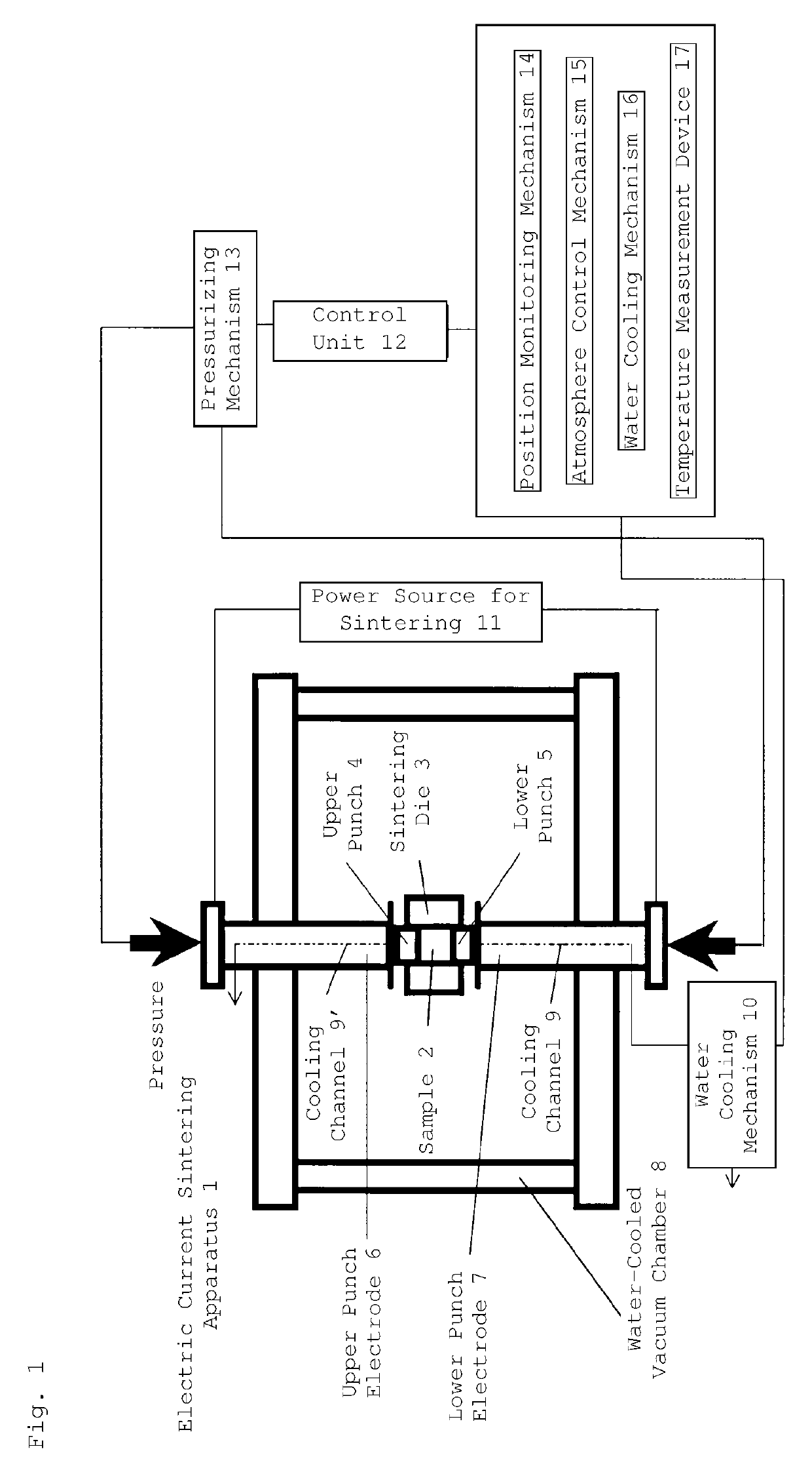
[0099]Commercially available spongy iron (Fe) (Junsei Chemical Co., Ltd., mean particle size: about 30 μm), commercially available red phosphorus (P) (Kishida Chemical Co., Ltd., mean particle size: about 20 μm), and commercially available sulfur (S) (Wako Pure Chemical Industries, Ltd., mean particle size: about 20 μm) were mixed to give a molar ratio of 1:2:6, and then heated at 550° C., thereby preparing iron phosphorus trisulfide (FePS3). This FePS3 and commercially available lithium sulfide (Mitsuwa Chemicals Co., Ltd., Li2S, mean particle size: about 16 μm) were weighed to give a molar ratio of 1:4 in an argon gas atmosphere in a glove box (dew point: −80° C.), fully mixed in a mortar, and packed into a graphite die having an inner diameter of 15 mm.

[0100]Subsequently, the graphite die filled with the starting materials was placed in an electric current sintering apparatus. The graphite die and the current-carrying part, which contains electrode portions, were housed in a vacu...

example 2

[0110]The procedure of Example 1 was repeated, except that the molar ratio of FePS3 to lithium sulfide (Li2S) was 1:5 and the heating treatment was performed at 1200° C. with an electric current sintering apparatus, thereby preparing a lithium-iron-phosphorus-sulfur-carbon composite. The proportion (atomic %) of each element used for the starting materials (in the composite) was as follows: Li 42.0%, Fe 4.2%, P4.2%, S 33.6%, and C 16.0%.

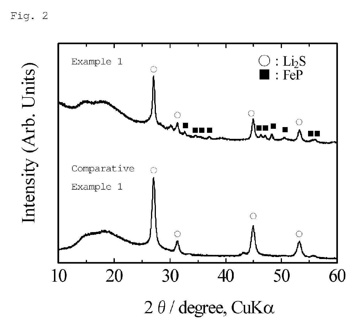
[0111]FIG. 4 shows an X-ray diffraction pattern of the obtained sample. As shown in FIG. 4, the peaks assigned to Li2S were observed as the main phase, and the peaks of FeP were also observed as a trace amount of impurities. The proportion (mol %) of FeP estimated in Rietveld analysis was about 4.4% (i.e., the proportion of Li2S was 95.6 mol %). The crystallite size estimated from the half-width of the diffraction peak based on the (111) plane of Li2S was about 47 nm. As described, this method prepared a lithium-iron-phosphorus-sulfur-carbon composit...

example 3

[0117]Exactly the same procedure as in Example 2 was repeated, except that the molar ratio of FePS3 to lithium sulfide (Li2S) was 1:6, thereby preparing a lithium-iron-phosphorus-sulfur-carbon composite. The proportion (atomic %) of each element used for the starting materials (in the composite) was as follows: Li 44.0%, Fe 3.7%, P 3.7%, S 33.0%, and C 15.6%.

[0118]FIG. 6 shows an X-ray diffraction pattern of the obtained sample. As shown in FIG. 6, the peaks assigned to Li2S were observed as the main phase, and the peaks of FeP were also observed as a trace amount of impurities. The proportion (mol %) of FeP estimated in Rietveld analysis was about 0.1% (i.e., the proportion of Li2S was 99.9 mol %). The crystallite size estimated from the half-width of the diffraction peak based on the (111) plane of Li2S was about 41 nm. As described, this method prepared a lithium-iron-phosphorus-sulfur-carbon composite containing lithium sulfide as the main phase with a crystallite size of 50 nm ...


PUM

PropertyMeasurementUnit
crystallite sizeaaaaaaaaaa

Abstract

A composite containing phosphorus, lithium, iron, sulfur, and carbon as constituent elements wherein lithium sulfide (Li2S) is present in an amount of 90 mol % or more, and wherein the crystallite size calculated from the half-width of a diffraction peak based on the (111) plane of Li2S as determined by X-ray powder diffraction measurement is 80 nm or less. The composite exhibits a high capacity (in particular, a high discharge capacity) useful as an electrode active material for a lithium-ion secondary battery (in particular, a cathode active material for a lithium-ion secondary battery), without the need for stepwise pre-cycling treatment.

Description

CROSS REFERENCE TO RELATED APPLICATIONS[0001]This application is the National Stage of International Application No. PCT / JP2015 / 082416, filed on Nov. 18, 2015, which claims the benefit of Japanese Application No. 2014-233711, filed on Nov. 18, 2014. The contents of both applications are hereby incorporated by reference in their entirety.TECHNICAL FIELD[0002]The present invention relates to a lithium-iron-phosphorus-sulfur-carbon composite, and a method for producing the composite.BACKGROUND ART[0003]Recent years have seen technical advances in portable electronic devices and hybrid vehicles etc., and there has been a growing demand for secondary batteries with a higher capacity (in particular, lithium-ion secondary batteries with a higher capacity) for use in those devices and vehicles. The development of high-capacity cathodes for lithium-ion secondary batteries currently lags behind that of high-capacity anodes. Even actively researched and developed high-capacity Li(Ni,Mn,Co)O2-b...

Claims


Application Information

Patent Timeline
Patent Type & Authority Patents(United States)
IPC IPC(8): H01M4/36H01M4/38C01G49/00H01M10/0525H01M4/583H01M4/136H01M4/134C01G49/12H01M10/0565H01M10/0562H01M10/052H01M4/58C01B17/22
CPCH01M4/364C01G49/00C01G49/12H01M4/134H01M4/136H01M4/36H01M4/38H01M4/58H01M4/583H01M4/5815H01M10/052H01M10/0525H01M10/0562H01M10/0565C01B17/22Y02T10/7011Y02E60/122Y02P70/54Y02E60/10C01P2002/72C01P2002/52C01P2002/54C01P2006/40C01P2002/60C01G49/009C01D15/00H01M4/362H01M4/1397H01M4/625C01P2004/64C01P2002/08C01P2002/70H01M2300/0068Y02P70/50Y02T10/70
Inventor TAKEUCHI, TOMONARIKAGEYAMA, HIROYUKISAKUDA, ATSUSHISAKAEBE, HIKARI
Owner NAT INST OF ADVANCED IND SCI & TECH
Learn More