
Ammonia separation method and zeolite

a technology of ammonia and separation method, which is applied in the field of ammonia separation method and zeolite, can solve the problems of low heat resistance of polymer membrane, low heat resistance of membrane, and easy swelling of polymer membrane, and achieve high ammonia gas permeability, high selectivity, and use stably

Active Publication Date: 2021-03-16
MITSUBISHI CHEM CORP
View PDF35 Cites 3 Cited by
  • Summary
  • Abstract
  • Description
  • Claims
  • Application Information

AI Technical Summary

Benefits of technology

The method enables efficient and selective separation of ammonia from mixed gases at high temperatures, reducing energy consumption and membrane area requirements, and is applicable to ammonia production processes like the Haber-Bosch process.

Problems solved by technology

While a polymer membrane has a feature that it is excellent in processability into, for example, a flat membrane or a hollow fiber membrane, there remains a technical problem that a polymer membrane is easily swelled and has low heat resistance.
A polymer membrane has low resistance to reactive chemicals, and there remains a technical problem that a polymer membrane easily deteriorates due to adsorptive components such as sulfides.
Furthermore, since a polymer membrane is easily deformed by pressure and the separation performance is thereby lowered, a polymer membrane is not practical in separation of ammonia under high temperature conditions, which is one of the problems of the present invention.
In particular, in the latter case, the concentration of ammonia gas contained in the generated mixed gas is inevitably low due to the reaction equilibrium limitation described above, and therefore, in a step of cooling and separating ammonia from the generated mixed gas, the cooling efficiency is poor and a great amount of energy is consumed.
In the process, it is necessary to separate a large amount of mixed gas of hydrogen gas and nitrogen gas from the generated mixed gas and recycle the separated gas to a reactor as raw material gas, and it is necessary to increase the pressure of the cooled, unreacted mixed gas to a predetermined pressure and the temperature of the gas to a reaction temperature, and therefore, the actual situation is that the energy consumption at the time of production is further increased.

Method used


Image

  • Ammonia separation method and zeolite
  • Ammonia separation method and zeolite

Examples


examples

[0302]Hereinafter, although the present invention is described more specifically based on Examples, the present invention is not limited by the following Examples without departing from the scope of the invention. The values of various production conditions and evaluation results in the following Examples have meanings as preferable values of the upper limit or the lower limit in an embodiment of the present invention, and a preferred range may be a range defined by a combination of the above-described upper limit or lower limit value and a value of the following Examples or a combination of values of Examples.

[0303]In the following, “CHA silicate zeolite” is simply called “CHA zeolite”, “RHO silicate zeolite” is simply called “RHO zeolite”, and “MFI silicate zeolite” is simply called “MFI zeolite”

example a

[Measurement of Separation Performance]

[0304]In the following, the separation performance of a zeolite membrane composite was measured as follows.

(1) Ammonia Separation Test

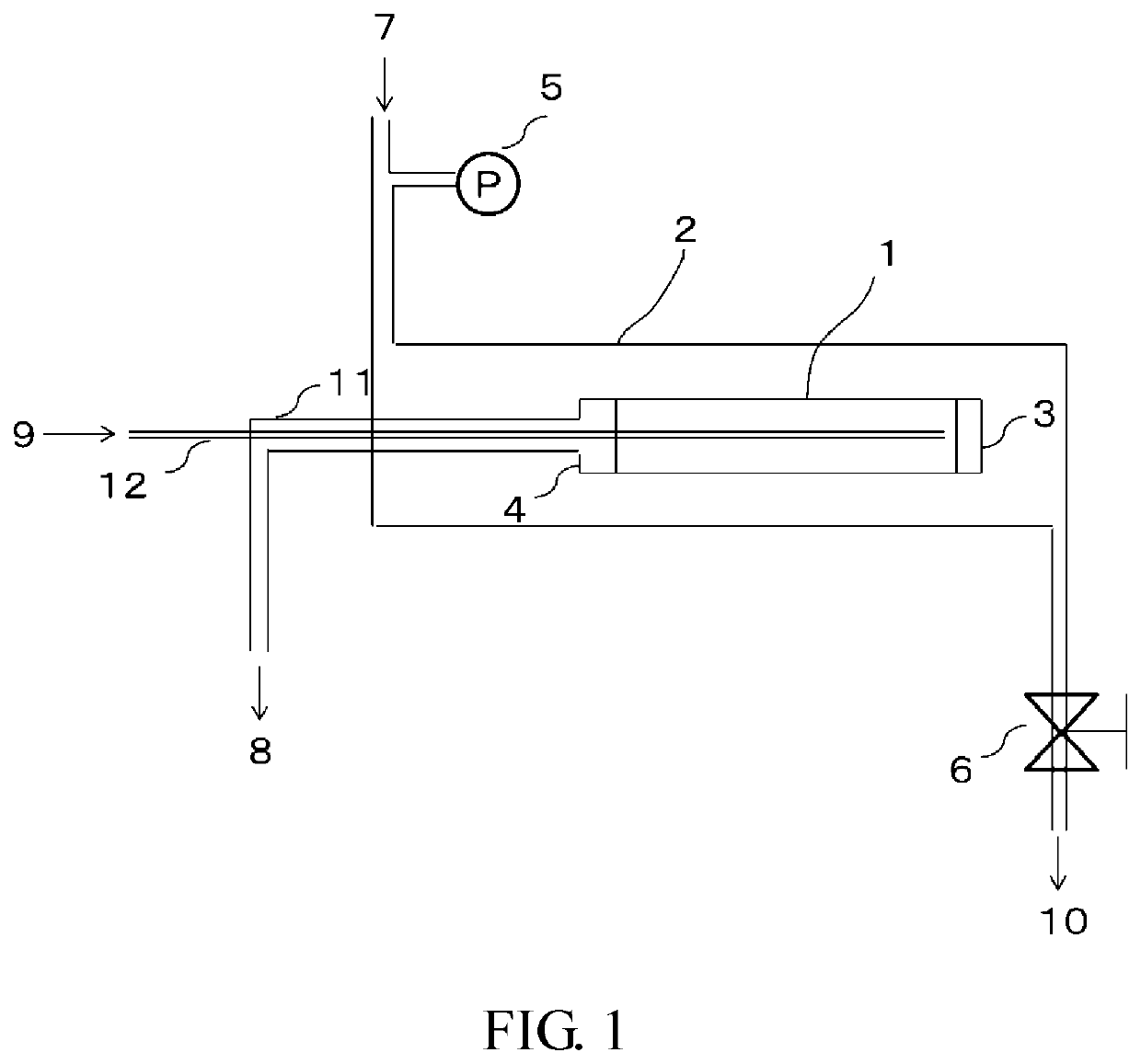
[0305]In an apparatus schematically shown in FIG. 1, an ammonia separation test was performed as follows. In the apparatus of FIG. 1, a mixed gas containing ammonia gas (NH3), nitrogen gas (N2), and hydrogen (H2) was supplied as a supply gas at a flow rate of 100 SCCM between a pressure vessel and a zeolite membrane composite, a back pressure valve was adjusted in such a manner that the pressure difference between gas on the supply side and gas permeated through a membrane was constant at 0.3 MPa, an exhaust gas discharged from a pipe 10 was analyzed with a micro gas chromatograph, and the concentration and flow rate of the permeated gas were calculated.

[0306]In an ammonia separation test, in order to remove components such as moisture and air from a pressure vessel, after purging with a sample gas to be used for...

production example a1

lite Membrane Composite 1

[0309]A CHA zeolite membrane composite 1 was produced by the following method.

(Raw Material Mixture for Hydrothermal Synthesis)

[0310]First, a raw material mixture for hydrothermal synthesis was prepared as follows.

[0311]To a mixture of 1.45 g of 1 mol / L-NaOH aqueous solution, 5.78 g of 1 mol / L-KOH aqueous solution, and 114.6 g of water, 0.19 g of aluminum hydroxide (containing Al2O3-53.5% by mass, manufactured by Aldrich Co., Ltd.) was added and dissolved by stirring to obtain a transparent solution. To this, 2.43 g of a 25% by mass aqueous solution of TMADAOH was added as an organic template, and then 10.85 g of colloidal silica (Snowtech-40, manufactured by Nissan Chemical Co., Ltd.) was added and stirred for 2 hours to obtain a raw material mixture for hydrothermal synthesis. The composition (molar ratio) of this mixture was SiO2 / Al2O3 / NaOH / KOH / H2O / TMADAOH=1 / 0.018 / 0.02 / 0.08 / 100 / 0.04, SiO2 / Al2O3=58.

(Support)

[0312]As a porous support, an alumina tube BN1 (o...


PUM


Abstract

Provided is a method for separating ammonia gas using zeolite membrane having excellent separation stability at a high temperature capable of separating ammonia gas from a mixed gas composed of multiple components including ammonia gas, hydrogen gas, and nitrogen gas to the permeation side with high selectivity and high permeability. Also provided is a method for separating ammonia by selectively permeating ammonia gas from a mixed gas containing at least ammonia gas, hydrogen gas, and nitrogen gas using a zeolite membrane, wherein the ammonia gas concentration in the mixed gas is 1.0% by volume or more.

Description

CROSS-REFERENCE TO RELATED APPLICATION[0001]This is a continuation of International Application PCT / JP2018 / 023042, filed on Jun. 15, 2018, and designated the U.S., and claims priority from Japanese Patent Application 2017-117862 which was filed on Jun. 15, 2017, Japanese Patent Application 2017-239295 which was filed on Dec. 14, 2017, Japanese Patent Application 2018-007414 which was filed on Jan. 19, 2018, Japanese Patent Application 2018-007415 which was filed on Jan. 19, 2018, and Japanese Patent Application 2018-007416 which was filed on Jan. 19, 2018, the entire contents of which are incorporated herein by reference.TECHNICAL FIELD[0002]The present invention relates to a method for separating ammonia by using a zeolite membrane to selectively allow ammonia gas to permeate, from a mixed gas composed of a plurality of components including ammonia gas, and hydrogen gas, and / or nitrogen gas. The present invention relates to a zeolite membrane that effectively separates ammonia from...

Claims


Application Information

Patent Timeline
Patent Type & Authority Patents(United States)
IPC IPC(8): B01D53/22B01D69/02B01D69/10B01D71/02
CPCB01D53/228B01D69/02B01D69/10B01D71/028B01D2257/406B01D2325/22B01D53/22C01B39/48C01C1/12C01C1/0458B01D67/0051Y02P20/52B01D71/0281B01D69/108
Inventor TANAKA, MANABUMATSUO, TAKESHIAOSHIMA, TAKAYUKI
Owner MITSUBISHI CHEM CORP
Learn More