Coolant for composite materials

a composite material and coolant technology, applied in the field of coolants, can solve the problems of high degree of tool wear, and high degree of tool wear, and achieve the effects of reducing friction and consequently tool wear, facilitating heat dissipation, and reducing health risks

Active Publication Date: 2022-04-12
RHENUS LUB
View PDF10 Cites 0 Cited by
  • Summary
  • Abstract
  • Description
  • Claims
  • Application Information

AI Technical Summary

Benefits of technology

[0020]Use of the said cooling lubricants facilitates the dissipation of heat resulting from the machining process; a lubricating effect between the relevant tools and materials reduces friction and consequently tool wear. At the same time, dust suppression reduces health risks. Moreover, it is possible to enhance the cutting speed, feed rate and machining quality during the machining process. This also results in a decrease in the number of rejects and longer tool life. Summing up, it can be said that the use of coolants in machining processes involving fiber-reinforced plastics is instrumental in improving efficiency, productivity and occupational health and safety.DETAILED DESCRIPTION OF PREFERRED EMBODIMENTS
[0021]The said coolant in the form of an emulsion is a mineral-oil-based, EP (extreme-pressure) coolant that contains no boron and no formaldehyde depot substances. It is available in the form of an emulsion with very good flushing properties. It is suited for machining fiber-reinforced plastics as well as for machining material combinations involving plastics / fiber-reinforced plastics and aluminum, steel and / or titanium. In its application concentration, the said coolant displays a high rate of foam decomposition. Furthermore, the said coolant displays good aluminum and skin compatibility and is also characterized by a pleasant odor.

Problems solved by technology

Often, delamination and protruding, uncut fibers are common finishing flaws resulting from the dry machining process.
Owing to the abrasiveness of the hard fibers, the degree of tool wear is high.
As a result, expensive tools made of polycrystalline diamond or manufactured with special coatings and geometric designs need to be used.
Without these tools, the machining process involving such materials is subject to many limitations.
This, however, would facilitate the corrosion of the tools, workpieces and machines used.
The specific challenge in this regard is the presence of different materials in the composite.
At present, composite manufacturers and the finishing industry still have many reservations and are reluctant to see the widespread use of coolants in machining processes involving CFRPs.
Consequently, there are concerns that the components of the lubricant can compromise the strength of the composite material or that there can be a potential concentration of lubricant components in the composite matrix which could have a negative impact on the mechanical properties of the composite.

Method used


Image

  • Coolant for composite materials
  • Coolant for composite materials
  • Coolant for composite materials

Examples


example 1

on of the Coolant (Emulsion)

[0050]The composition of a feasible concentrate of the coolant according to the invention is shown in the following table. The substances specified in the table are to be mixed together under vigorous stirring. The figures in the table represent % by weight based on the weight of the coolant concentrate that is in the form of an emulsion.

[0051]

Water11.42Monoisopropanolamine2Methyl diethanolamine10Triethanolamine (pure, 90%)9.7Benzotriazole (corrosion inhibitor)0.9IRGACOR ® L 190-85 (corrosion inhibitor)2.1Mineral oil6Phenoxyethanol10SNS 520 (corrosion inhibitor)5TPS 20 (dialkyl sulfide)4TPS 32 (dialkyl sulfide)8Edenol ® D 81 (epoxidized ester)4Lubrhophos ® LB 400 E ALL (phosphoric acid ester)2Diacid ® 1550 (corrosion inhibitor)3Fosfodet ® RS 0602 (alkyl phosphate)4AC 101 (corrosion inhibitor)4Emulsifier9Maleic acid dibutyl ester4Benzisothiazolinone0.49Butylbenzisothiazolinone0.09Defoamer0.3

[0052]For application purposes, the concentrate is to be diluted w...

example 2

on of the Coolant (Solution)

[0053]The composition of a feasible water-soluble concentrate of the coolant according to the invention is shown in the following table. The substances specified in the table are to be mixed together under vigorous stirring. The figures in the table represent % by weight based on the weight of the coolant concentrate

[0054]

Water34.11IRGACOR ® L 190-85 (corrosion inhibitor)4Monoethanolamine6.9Triethanolamine30Sebacic acid (corrosion inhibitor)3Isononanoic acid (corrosion inhibitor)5Tolyltriazole0.7BREOX 75W 2050 (PAG)15Defoamer0.2Iodocarbamate0.6Benzisothiazolinone0.49

[0055]For application purposes, the concentrate is to be diluted with water in a weight ratio of 1:9.

example 3

est for Drilling

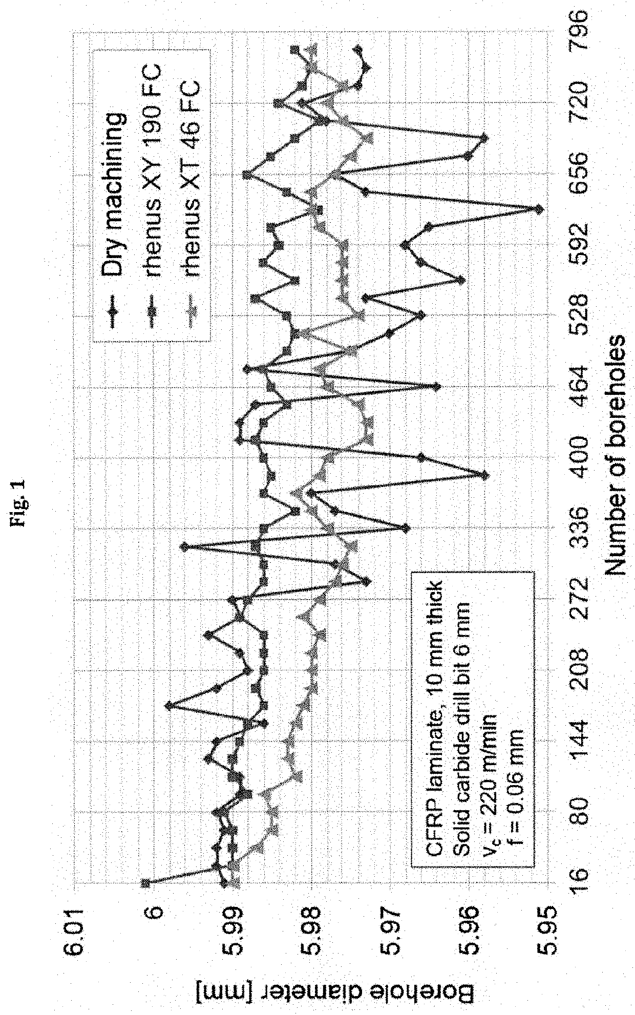
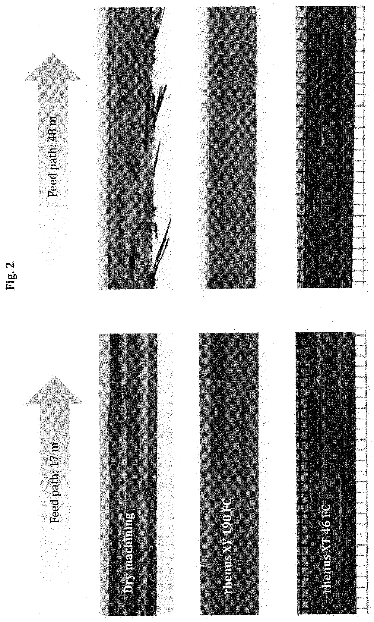
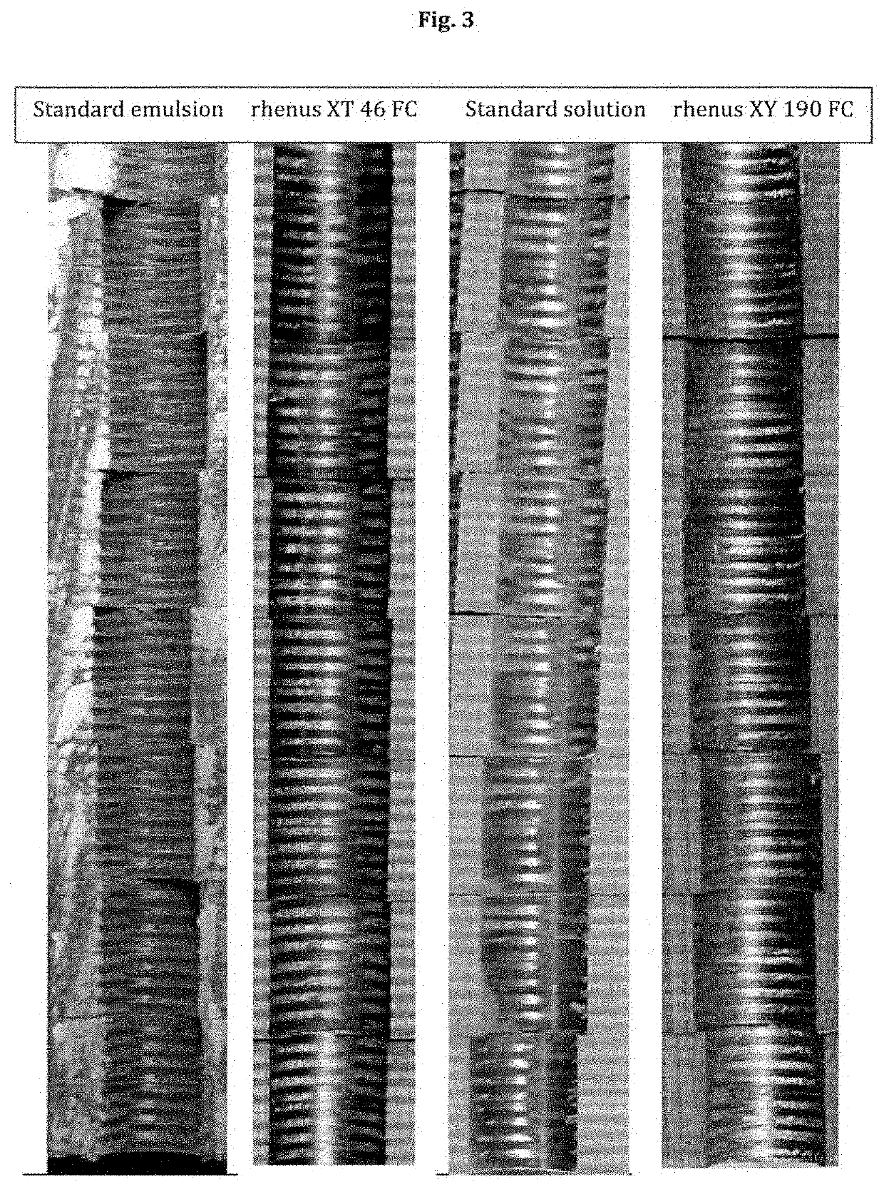
[0056]The machining quality for drilling of a 10-mm-thick carbon fiber-reinforced plastic plate was tested in three runs: without a coolant, with the coolant according to the invention, called rhenus XT 46 FC (Example 1), and with a fully water-soluble coolant, called rhenus XY 190 FC in FIG. 1. For each of the three test runs, a new, solid carbide, 6-mm drill bit was used at a drilling speed Vc of 120 m / min. More than 720 holes were drilled with each bit and the diameter of the boreholes was subsequently determined. The graph in FIG. 1 shows that, during the dry drilling process without the use of a coolant, an increase in the number of boreholes also results in greater fluctuations in the borehole diameter. These fluctuations in terms of the borehole diameter are significantly greater in contrast to drilling operations with a coolant.


PUM

PropertyMeasurementUnit
kinematic viscosityaaaaaaaaaa
thicknessaaaaaaaaaa

Abstract

The present invention concerns a coolant, present as an emulsion in the form of a concentrate, for machining fiber-reinforced plastics and material combinations containing fiber-reinforced plastics and metals; furthermore, the present invention also concerns a coolant, present as a solution in the form of concentrate, for machining fiber-reinforced plastics.

Description

TECHNICAL FIELD OF THE INVENTION[0001]This invention pertains to coolants for the processing of fiber-reinforced plastics and material combinations and composites involving fiber-reinforced plastics and metals and to a method for processing such materials.BACKGROUND OF THE INVENTION[0002]The use of coolants in machining is widespread in the metalworking industry. The cooling and lubricating effect not only increases the service life of the tools but also improves the surface quality of the machined components. As of today, coolants are only used sporadically for machining operations involving fiber-reinforced plastics. According to a study carried out in 2014, more than 50% of users implement dry machining processes when it comes to CFRPs and only 16% implement flood coolant procedures. Owing to the extremely minute, respirable particles, dry machining processes need to be carried out in proper enclosures. Furthermore, an extraction of the FRP dust from the cutting machines is also ...

Claims


Application Information

Patent Timeline
Patent Type & Authority Patents(United States)
IPC IPC(8): C10M169/04C10M173/02C10M173/00C10M105/72C10M129/16C10M129/40C10M129/42C10M129/68C10M129/72C10M133/08C10M133/44C10M135/22C10M135/36C10M137/04C10M141/10C10N20/02C10N20/04C10N20/00C10N30/06C10N30/12C10N30/16C10N30/18C10N30/00C10N40/00C10N40/22C10N50/00
CPCC10M169/04C10M105/72C10M129/16C10M129/40C10M129/42C10M129/68C10M129/72C10M133/08C10M133/44C10M135/22C10M135/36C10M137/04C10M141/10C10M173/00C10M173/02B23B2250/12C10M2201/02C10M2201/085C10M2203/10C10M2207/04C10M2207/046C10M2207/126C10M2207/127C10M2207/24C10M2207/28C10M2207/282C10M2209/086C10M2209/107C10M2209/1075C10M2215/042C10M2215/10C10M2215/223C10M2215/26C10M2215/30C10M2219/022C10M2219/024C10M2219/082C10M2219/104C10M2219/106C10M2223/04C10M2223/043C10M2225/04C10N2020/02C10N2020/04C10N2020/091C10N2030/06C10N2030/12C10N2030/16C10N2030/18C10N2030/24C10N2040/00C10N2040/22C10N2050/01C10N2050/013C10M2209/104C10M2209/105C10M2209/1045C10M2209/1055
Inventor DEMMERLING, ANNA LENASCHLINDWEIN, HANS JÜRGENHEDIGER, THOMASQUOTSCHALLA, UDO
Owner RHENUS LUB
Why Eureka
Try Eureka