

Grafted polymer electrolyte membrane, method of producing a grafted polymer electrolyte membrane, and fuel cell comprising the same
a polymer electrolyte and polymer electrolyte technology, which is applied in the direction of non-aqueous electrolyte cells, sustainable manufacturing/processing, and final product manufacturing, etc., can solve the problems of difficult fluorocarbon-type polymer electrolyte membrane, degrade fuel cell performance, and affect the performance of the fuel cell
- Summary
- Abstract
- Description
- Claims
- Application Information
AI Technical Summary
Benefits of technology
Problems solved by technology
Method used
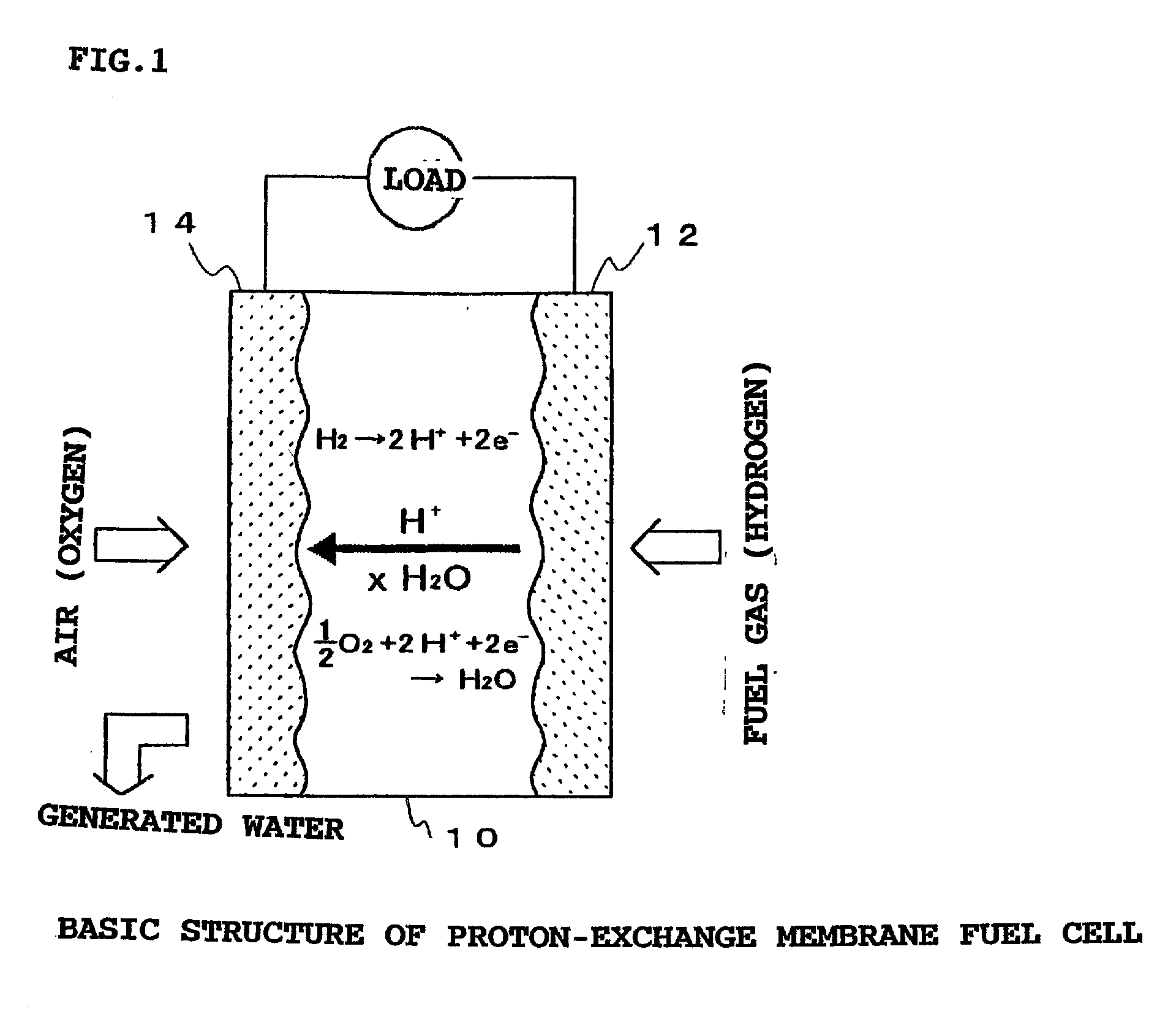
Image

Examples
first embodiment
[0039] The detailed process for producing the sulfonic acid type ETFE-g-PSt electrolyte membrane of the First Embodiment is as follows. An ETFE membrane having a thickness of 100 .mu.m and dimensions of 100 mm.times.100 mm was exposed to a plasma in an oxidative atmosphere in a plasma reactor provided by Yamato Kagaku Co. Ltd. The plasma treatment conditions were as follows: ambient gas composition-argon:oxygen=75:25, gas flow rate-90 ml / min, output-30 W, and process time-20 seconds. The resulting plasma treated ETFE membrane was then cooled with dry ice and maintained at a cooled temperature. The cooled ETFE membrane was then irradiated with a high energy electron beam at 2 MeV and 20 kGy to produce radicals in the ETFE membrane. The irradiated ETFE membrane was then warmed to room temperature, and immediately immersed in an excess amount of styrene monomer in a nitrogen purged reaction vessel. The membrane and styrene monomer mixture was then warmed at 60.degree. C. for about 60 h...
second embodiment
[0043] The sulfonic acid type PVDF-g-PSt electrolyte membrane of the Second Embodiment was produced according to the method described in the First Embodiment, above, except that the precursor membrane was a polyvinylidenedifluoride membrane (PVDF membrane) rather than an ETFE membrane. The PVDF membrane of the Second Embodiment was plasma treated under oxidizing conditions, graft-polymerized with polystyrene, then sulfonic acid groups were introduced therein, as described above.
[0044] The detailed process of producing the sulfonic acid type PVDF-g-PSt electrolyte membrane of the Second Embodiment is as follows. A PVDF membrane having a thickness of 100 .mu.m and dimensions of 100 mm.times.100 mm was exposed to a plasma in an oxidative atmosphere using a plasma reactor provided by Yamato Kagaku Co. Ltd. The plasma treatment conditions were as follows: ambient gas composition-argon:oxygen=75:25, gas flow rate-90 ml / min, output-30W, and process time-20 seconds. The resulting PVDF membr...
PUM
| Property | Measurement | Unit |
|---|---|---|
| thickness | aaaaa | aaaaa |
| thickness | aaaaa | aaaaa |
| temperature | aaaaa | aaaaa |
Abstract
Description
Claims
Application Information