
Apparatus and methods for controlled substance delivery from implanted prostheses

Inactive Publication Date: 2002-06-27
ALTAI MEDICAL TECH
View PDF1 Cites 151 Cited by
  • Summary
  • Abstract
  • Description
  • Claims
  • Application Information

AI Technical Summary

Benefits of technology

[0017] The predetermined time pattern of the present invention improves the efficiency of drug delivery by releasing a lower or minimal amount of the substance until a subsequent phase is reached, at which point the release of the substance may be substantially higher. Thus, time delayed substance release can be programmed to impact restenosis substantially at the onset of events leading to smooth muscle cell proliferation (hyperplasia), The present invention can further minimize substance washout by timing substance release to occur after at least initial cellularization and / or endothelialization which creates a barrier over the stent to reduce loss of the substance directly into the bloodstream. Moreover, the predetermined time pattern may reduce substance loading and / or substance concentration as well as potentially providing minimal to no hindrance to endothelialization of the vessel wall due to the minimization of drug washout and the increased efficiency of substance release.
[0019] It will be appreciated that the above-described benefits of time delayed release allow for a wide array of substances to be effectively delivered. The substance may comprise at least one agent selected from the group consisting of immunosuppressant agent, anti-inflammatory agent, anti-proliferative agent, anti-migratory agent, anti-fibrotic agent, anti-thrombotic agent, anti-platelet agent, and IIb / IIIa agent. Preferably, the agent is an immunosuppressant agent selected from the group consisting of mycophenolic acid, rapamycin, cyclosporine A, cycloheximide, cyclophoshamide, mizoribine, methylprednisolone, azathioprine, ribovirin, FK506, tiazofurin, methotrexate, zafurin, and mycophenolate mofetil. The total amount of substance released will typically be in a range from 1 .mu.g. to 2000 .mu.g., preferably in a range from 10 .mu.g. to 1000 .mu.g., most preferably in a range from 50 .mu.g. to 500 .mu.g. The release rate during the initial phase will typically be from 0 .mu.g / day to 50 .mu.g / day, usually from 5 .mu.g / day to 30 .mu.g / day. The substance release rate during the subsequent phase will be much higher, typically being in the range from 5 .mu.g / day to 200 .mu.g / day, usually from 10 .mu.g / day to 100 .mu.g / day. Thus, the initial release rate will typically be from 0 % to 99 % of the subsequent release rates, usually from 0% to 90%, preferably from 0% to 75%. Of course, the release rates may vary during either or both of the initial and subsequent release phases. There may also be additional phase(s) for release of the same substance(s) and / or different substance(s).
[0024] Additionally, a rate limiting barrier may be formed adjacent to the scaffold and / or the matrix. Such rate limiting barriers may be nonerodible or nondegradable, such as silicone, polytetrafluorethylene (PTFE), paralene, and parylast, and control the flow rate of release passing through the rate limiting barrier. In such a case, the substance may be released by diffusion through the rate limiting barrier. Furthermore, a biocompatible or blood compatible layer, such as polyethylene glycol (PEG), may be formed over the matrix or rate limiting barrier to make the delivery prosthesis more biocompatible.
[0028] In a fourth embodiment, the means for releasing the substance comprises a reservoir on or within the scaffold containing the substance and an external energy source for directing energy at the prosthesis after implantation to effect release of the substance. A matrix or barrier may be formed adjacent to the reservoir to contain the substance within the reservoir. Alternatively, the means for releasing the substance may comprise a matrix or rate limiting barrier formed over at least a portion of the scaffold, wherein the substance is disposed adjacent or within the matrix or barrier, and an external energy source for directing energy at the prosthesis after implantation to effect release of the substance. The external energy source may comprise ultrasound, magnetic resonance imaging, magnetic field, radio frequency, temperature change, electromagnetic, x-ray, radiation, heat, gamma, or microwave. Exposure of the prosthesis to an external energy source may change a porosity, diffusion rate, hydrophilicity, or hydrophobicity of the prosthesis, thus allowing release of the substance over the predetermined time pattern.

Problems solved by technology

Additionally, a rate limiting barrier may be formed adjacent to the scaffold and / or the matrix.

Method used


Image

  • Apparatus and methods for controlled substance delivery from implanted prostheses
  • Apparatus and methods for controlled substance delivery from implanted prostheses
  • Apparatus and methods for controlled substance delivery from implanted prostheses

Examples


Embodiment Construction

[0052] The present invention provides improved devices and methods for inhibiting restenosis and hyperplasia after intravascular intervention. In particular, the present invention provides luminal prostheses which allow for programmed and controlled substance delivery with increased efficacy to selected locations within a patient's vasculature to inhibit restenosis.

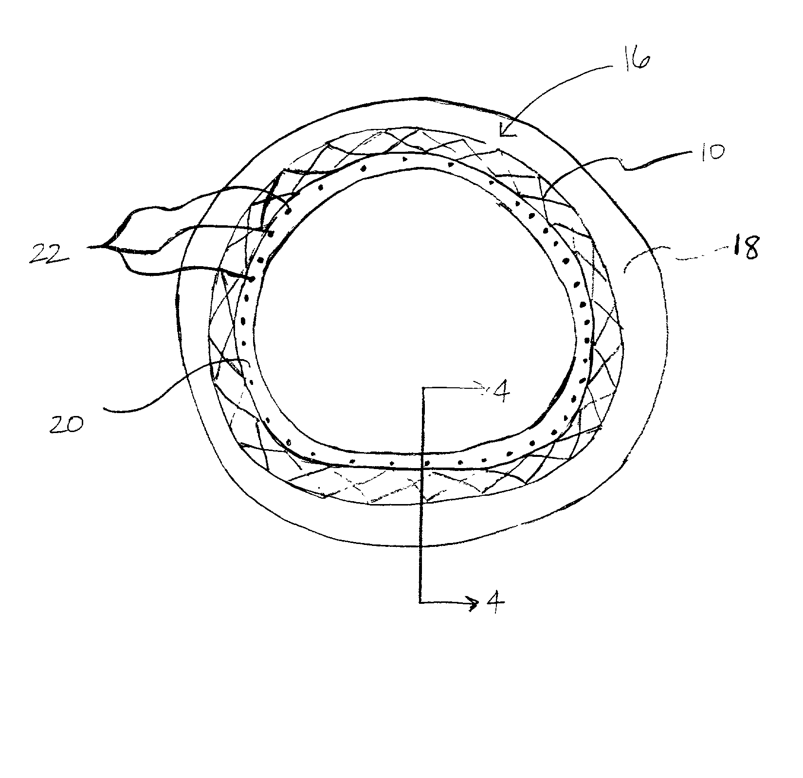
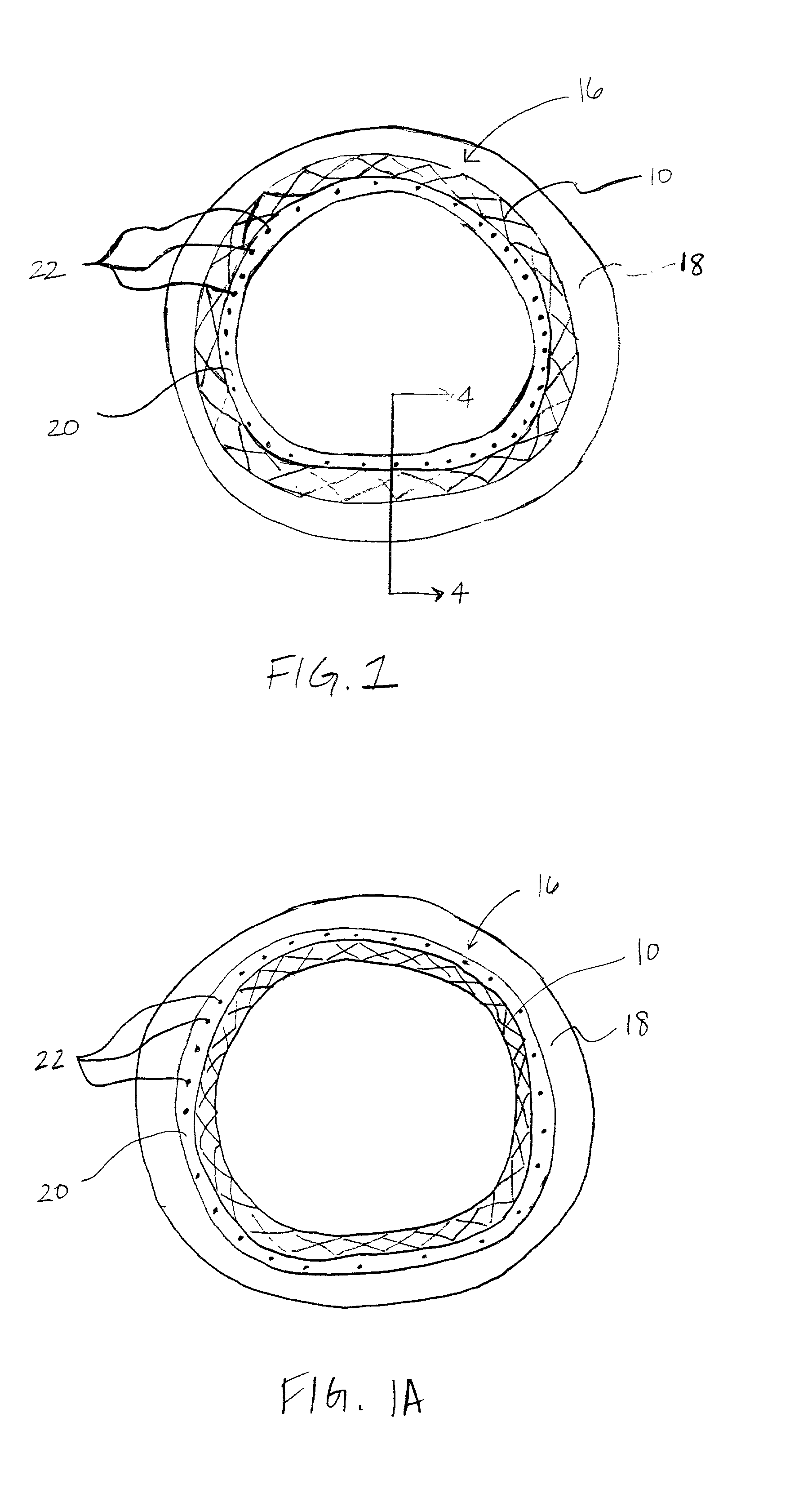
[0053] FIGS. 1 and 1A illustrate a delivery prosthesis 16 constructed in accordance with the principles of the present invention. The luminal delivery prosthesis 16 comprises a scaffold 10 which is implantable in a body lumen 18 and means 20 on the scaffold 10 for releasing a substance 22. The substance 22 is released over a predetermined time pattern comprising an initial phase wherein the substance delivery rate is below a threshold level and a subsequent phase wherein the substance delivery rate is above a threshold level.

[0054] It will be appreciated that the following depictions are for illustration purposes only and...


PUM


Abstract

The present invention provides improved devices and methods for inhibiting restenosis and hyperplasia after intravascular intervention. In particular, the present invention provides luminal prostheses which allow for programmed and controlled substance delivery with increased efficacy to selected locations within a patient's vasculature to inhibit restenosis. The luminal delivery prosthesis comprises a scaffold which is implantable within a body lumen and means on the scaffold for releasing a substance from the scaffold. The substance is released over a predetermined time pattern comprising an initial phase wherein the substance delivery rate is below a threshold level and a subsequent phase wherein the substance delivery rate is above a threshold level.

Description

CROSS-REFERENCES TO RELATED APPLICATIONS[0001] This application claims the benefit of Provisional Application No. 60 / 258,024, filed Dec. 22, 2000, under 37 C.F.R. .sctn.1.78(a)(3), the full disclosure of which is incorporated herein by reference.[0002] 1. Field of the Invention[0003] The present invention relates generally to medical devices and methods. More particularly, the present invention provides luminal prostheses, such as vascular stents and grafts, which allow for controlled substance delivery for inhibiting restenosis in a blood vessel following balloon angioplasty or other interventional treatments.[0004] A number of percutaneous intravascular procedures have been developed for treating stenotic atherosclerotic regions of a patient's vasculature to restore adequate blood flow. The most successful of these treatments is percutaneous transluminal angioplasty (PTA). In PTA, a catheter, having an expansible distal end usually in the form of an inflatable balloon, is position...

Claims


Application Information

Patent Timeline
IPC IPC(8): A61F2/00A61F2/90A61L27/54A61L31/16
CPCA61F2/90A61F2250/0067A61L27/54A61F2210/0076A61L2300/416A61L2300/602A61L31/16
Inventor SIRHAN, MOTASIMYAN, JOHN
Owner ALTAI MEDICAL TECH
Learn More