High efficiency ion exchange system for removing contaminants from water

Inactive Publication Date: 2002-08-29
HSBC BANK
View PDF9 Cites 30 Cited by
  • Summary
  • Abstract
  • Description
  • Claims
  • Application Information

AI Technical Summary

Benefits of technology

0027] A particular advantage of the invention is its ability to provide treated water with a markedly reduced amount of waste water being produced.
0028] We now have devised a fixed bed system for ion exchange water purification which embodies the advantages of a moving bed system without the size and cost of a moving bed design. The present design involves employing a substantial plurality (at least ten and preferably from about ten to about twenty-five) of fixed bed vessels which do not move but which can be accessed by the various process flows using a series of controller-actuatable valves, for example microprocessor-controlled valves. The system uses closely clustered, fixed position, multiple vessels combined with valves and piping so arranged to obtain the cost advantages of using small mass-produced vessels and valves, and a combination of easily maintained valves.
0029] The present invention achieves (1) high process efficiency, (2) process flexibility, (3) low wastewater production, and (4) construction compactness and maintenance ease.
0030] The invention uses several relatively small diameter fixed vessels each with two p

Problems solved by technology

In many cases, the water may also contain contaminants that are known to be detrimental to health.
Such ionic substances as nitrite, nitrate, arsenic, antimony, fluoride, selenate, chromate, perchlorate and other similar harmful substances are often found.
There are disadvantages, however, because larger vessels and large valves are required.
Operation and maintenance costs will rise when first equipment costs are low because of large vessels.
This step requires time and process water and produces additional waste water.
These systems eliminate the use of large vessels and the subsequent high maintenance and replacement costs.
Consequently, as the platform rotates, the process stream entering and leaving any of the vessels changes according to a predetermined and difficult to alter process flow, set by the multiport valves.
In many cases, the d

Method used


Image

  • High efficiency ion exchange system for removing contaminants from water
  • High efficiency ion exchange system for removing contaminants from water
  • High efficiency ion exchange system for removing contaminants from water

Examples


first embodiment

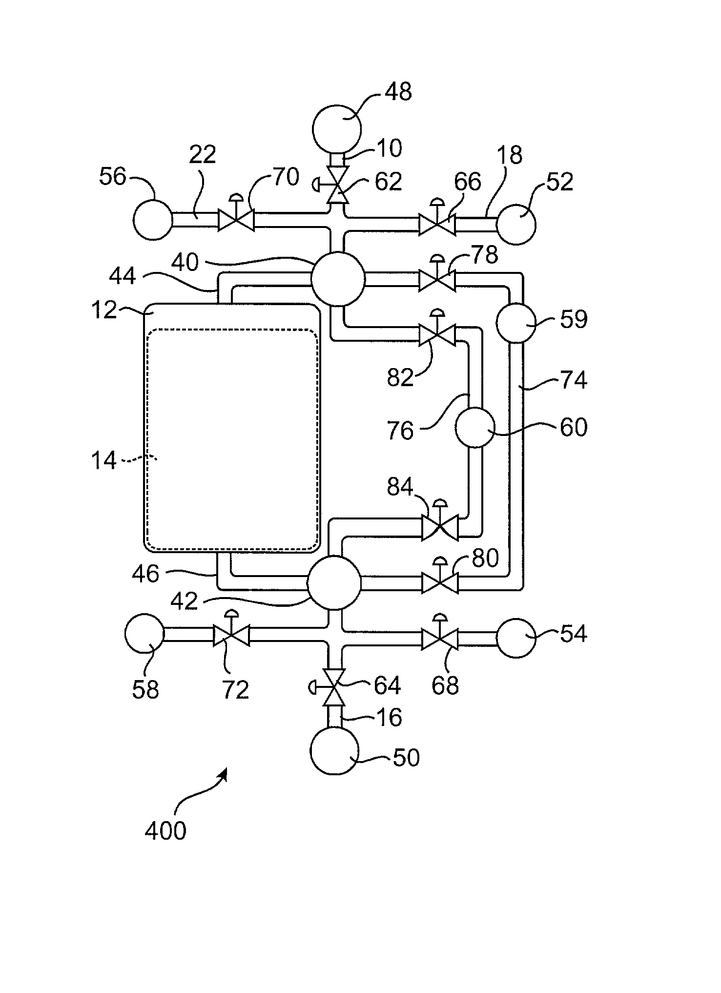
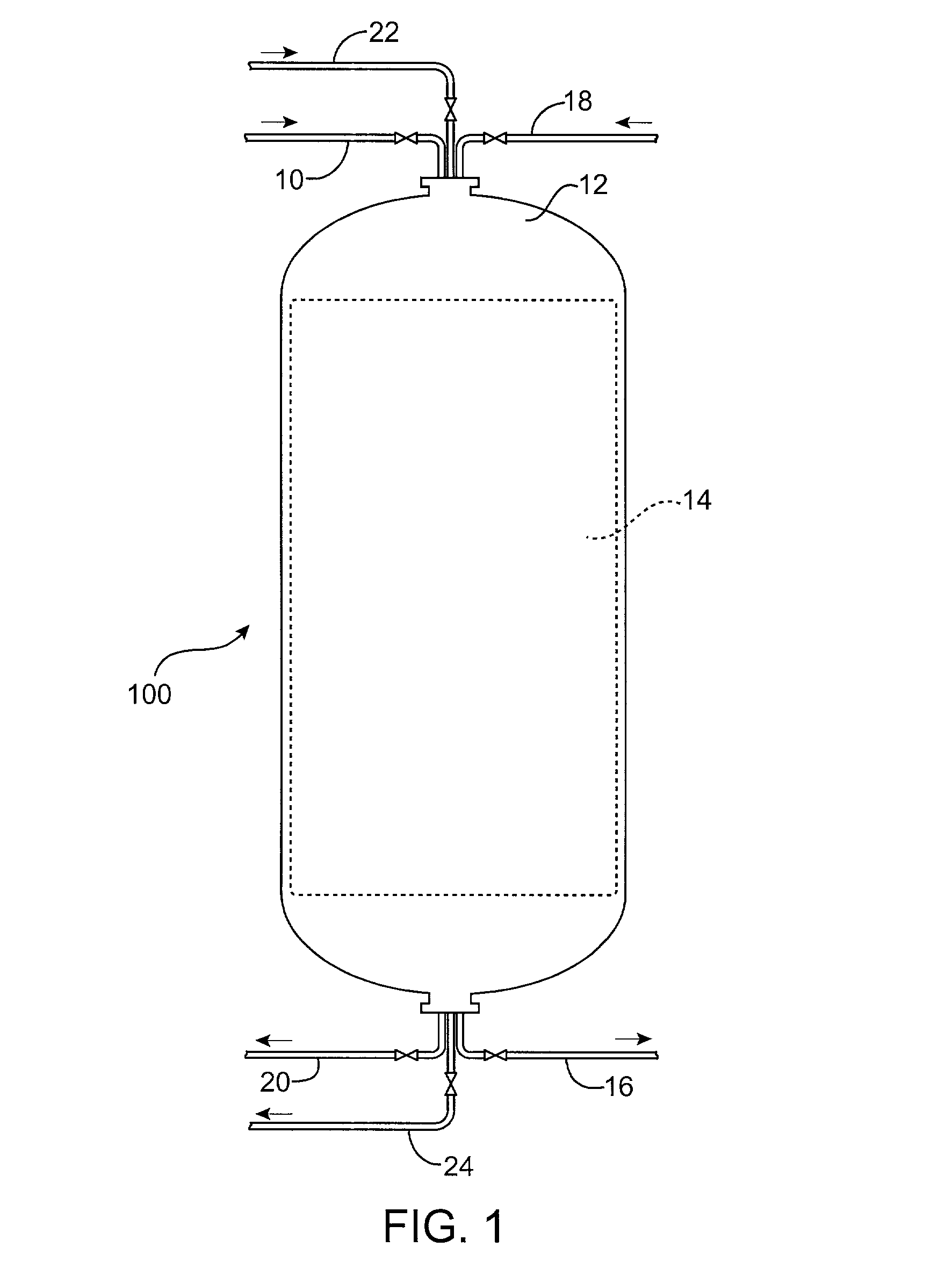
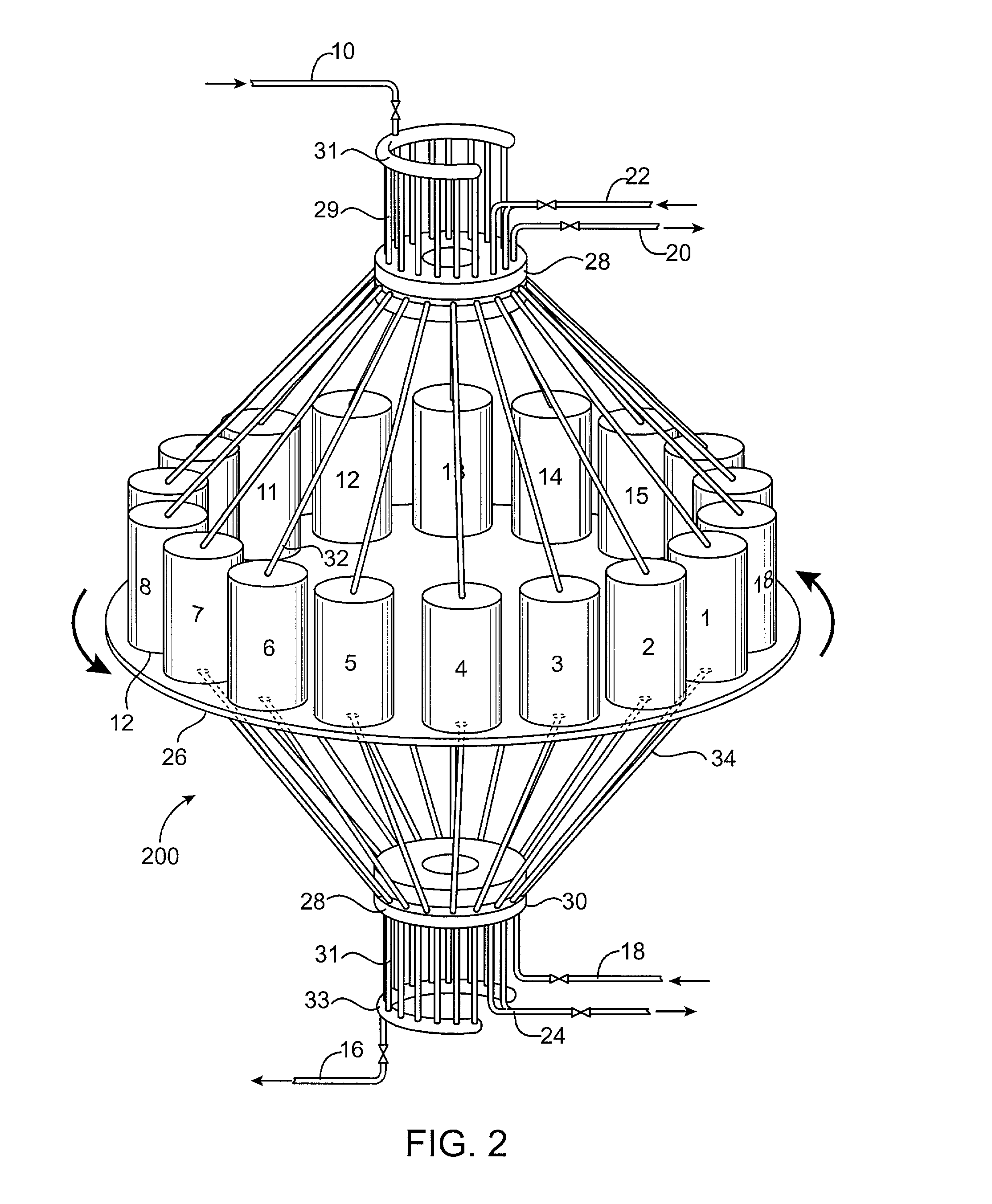
[0091] the overall system of the invention is shown in FIG. 7 as system 700. System 700 includes eighteen vessels 12-1 through 12-18, where eighteen is a representative number in the range of ten to twenty-five or greater. Each vessel is numbered with an identifier "1", "2" . . . "18" to identify its unique position in the overall system. Each vessel is configured for cocurrent flow of treatment water and regenerant essentially as set out in FIG. 5 and is equipped with headers, manifolds, lines and valves as described with reference to FIGS. 4 and 5. These elements are numbered in accord with the numbering used in FIGS. 4 and 5 with an added indication if a particular element is associated with a particular vessel. For example, header "40-1" is the "40" header associated with vessel 1.

[0092] Each of the eighteen vessels contains a bed of ion exchange resin and each has a header 40-1, etc which provides access to the vessel and to contaminated water supplied by feed manifold 48, via ...

second embodiment

[0105] the overall system of the invention is shown in FIG. 8 as system 800. System 800 includes sixteen vessels 12-1 through 12-16. The numbering of elements of the process is in accord with the numbering used with FIG. 7. Contaminated water is feeding through the resin beds in vessels 12-1 through 12-13. Purified water is being withdrawn from these thirteen vessels through headers 42-1 and valve 64-1, etc and collected in manifold 50 for use. Again, valves 64-1 through 64-13 all are shown with a dot to show a positive fluid flow.

[0106] Vessels 12-14 through 12-16 are not in service purifying water. The resin beds in vessels 12-15 and 16 are undergoing regeneration with a brine solution and the bed in vessel 12-14 is being rinsed to remove spent brine prior to being returned to service. As noted above, this regeneration could be carried out with substantial volumes of regenerant and rinse going to waste. It could also be carried out with substantially reduced waste, for example as ...

example 1

[0157] Nitrate Removal

[0158] This example shows the removal of nitrate ion from a ground water source as practiced on a continuous, pilot scale basis. A representative analysis of the feed water showed the following:

1 Typical Actual nitrate 45-200 mg / L 52 chloride 35-200 mg / L 44 sulfate 0-300 mg / L 100 bicarbonate 60-200 mg / L 98

[0159] The product water contained on average 6 mg / L of nitrate and less than 1 mg / L of sulfate.

[0160] The feed water was fed into a purification system substantially as shown in FIG. 7 as 700. Sixteen to eighteen vessels were used at various times during the run. Each vessel was 36 inches in diameter by 48 inches high. Each contained about 25 ft..sup.3 of an ion exchange resin. Commercial strong base type I an ion exchange resin having a DVB cross-linked polystyrene matrix and type I quaternary ammonium functional groups was used. This resin was in the form of beds of typical resin bed size {fraction (1 / 16)}-{fraction (1 / 64)} inch diameter. These vessels were...


PUM

PropertyMeasurementUnit
Fractionaaaaaaaaaa
Densityaaaaaaaaaa
Densityaaaaaaaaaa

Abstract

The disclosed invention is a fixed bed ion exchange water purification system. It employs a combination of electronically controlled process steps and specific systems configurations to duplicate the effects of moving resin beds from one operating position to another as is required in moving bed ion exchange water purification systems. The invention combines features of single fixed bed ion exchange systems with those of a moving bed system. The invention applies to the treatment of water having typical industrial and drinking water concentrations of various ions.

Description

[0001] This invention relates to ion exchange systems for removing contaminants from water. More particularly it relates to fixed bed ion exchange systems which are configured to yield the flexibility and efficiency of moving bed systems.BACKGROUND AND STATE OF THE ART[0002] Ion exchange is a chemical process often used to separate certain contaminant substances from a drinking water supply containing a mixture of several other harmless dissolved substances. For example, common ground water used for drinking water will contain substances such as the ionic forms of calcium, magnesium, sulfate, chloride and bicarbonate. In many cases, the water may also contain contaminants that are known to be detrimental to health. Such ionic substances as nitrite, nitrate, arsenic, antimony, fluoride, selenate, chromate, perchlorate and other similar harmful substances are often found. It is desirable to separate out the contaminants harmful to health by treating the water with an ion exchange syst...

Claims


Application Information

Patent Timeline
IPC IPC(8): B01J47/14B01J49/00C02F1/00C02F1/42C02F1/72C02F1/76
CPCB01J47/14B01J49/0004B01J49/0095C02F1/008C02F1/42C02F1/72C02F1/76C02F2101/10C02F2101/103C02F2101/12C02F2101/16C02F2101/163C02F2101/22C02F2209/005C02F2303/16Y10S210/912Y10S210/913Y10S210/903Y10S210/902B01J49/05B01J49/85
Inventor JENSEN, PETER L.GUTER, GERALD A.ZIOL, DAN
Owner HSBC BANK
Why Eureka
Try Eureka