Electroluminescent (EL) devices
a technology of electroluminescent devices and electroluminescent lamps, which is applied in the direction of discharge tubes/lamp details, natural mineral layered products, anthracene dyes, etc., can solve the problems of high inefficiency of up-shifting of tris(8-hydroxyquinolinate)al-uminum emission to the blue region, and the performance of a number of current available devices, especially with respect to blue emission, may still be below expectations, and achieves many disadvantages
- Summary
- Abstract
- Description
- Claims
- Application Information
AI Technical Summary
Benefits of technology
Problems solved by technology
Method used
Image
Examples
example i
Synthesis of 9-anthryl-4,4,5,5-tetramethyl-1,3,2-dioxaborolane
[0075] To a solution of 9-bromoanthracene (9.73 grams) in 100 milliliters of anhydrous diethyl ether were slowly added at about 0.degree. C. 23 milliliters of 2M n-butyllithium hexane solution. After the addition, the reaction mixture was warmed to room temperature (about 23.degree. C.) for 30 minutes. The resulting mixture was then cooled to around -30.degree. C. and 2-isopropoxy-4,4,5,5-tetramethyl-1,3,3-dioxaborolane (9.27 milliliters) was added through a syringe. The resulting reaction mixture was warmed to room temperature (about 23.degree. C.), and stirred overnight (about 18 hours throughout). After being diluted with 50 milliliters of hexane, the mixture resulting was filtered through celite. Removal of the solvents under reduced pressure yielded a yellowish solid (6.70 grams) which contains more than 90 percent of 9-anthryl-4,4,5,5-tetramethyl-1,3,2-dioxaborolane. The product may be used without further purificat...
example ii
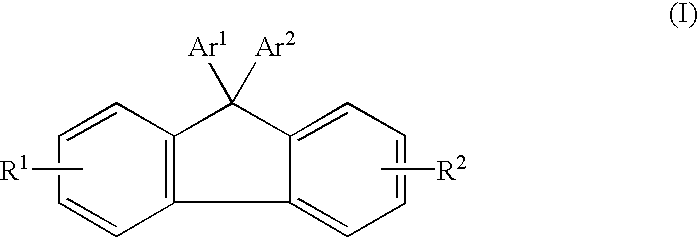
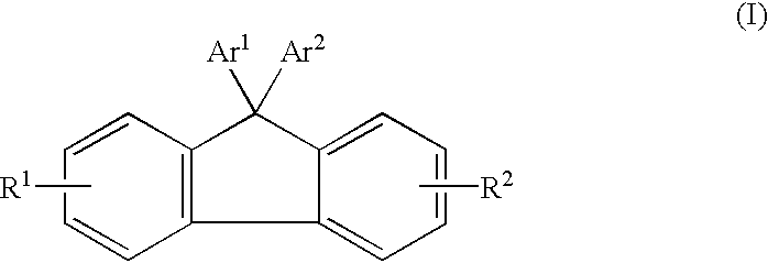
Synthesis of 4,4'-(9-fluorenylidene)diphenyl Ditriflate
[0076] To a solution of 4,4'-(9-fluorenyledene)diphenol (10 grams) in 100 milliliters of anhydrous pyridine were added at about 5.degree. C. grams 11 milliliters of triflic acid anhydride. After the addition, the reaction mixture was warmed to room temperature (about 23.degree. C.) for 6 hours. After removal of the pyridine under reduced pressure, the residue was dissolved in 200 milliliters of dichloromethane, washed with 5 percent HCI aqueous solution, followed by washing with water. After removal of the solvents, the resulting crude residue was purified through a silica column to yield 17.26 grams of 4,4'-(9-fluorenylidene)diphenyl ditriflate. This compound and its structure was confirmed by proton NMR analysis.
example iii
Synthesis of 9,9-bis[4-(9-anthryl)phenyl) fluorene
[0077] A mixture of 9-anthryl-4,4,5,5-tetramethyl-1,3,2-dioxaborolane (5 grams), 4,4'-(9-fluorenylidene)diphenyl ditriflate (5.3 grams), potassium carbonate (2.27 grams) in 50 milliliters of dioxane was purged with argon for 10 minutes. To this mixture was then added tetrakis(triphenylphosphin-e) palladium (0.37 gram). The reaction mixture was stirred at reflux for 48 hours under argon. After cooling to room temperature (about 23.degree. C.), the mixture was diluted with 30 milliliters of methanol, and the precipitates were collected by filtration, washed with 5 percent HCl aqueous solution, followed by water to remove inorganic salts. After drying, the filtrates were purified by sublimation to yield 2.5 grams of 9,9-bis[4-(9-anthryl)phenyl) fluorene. This compound had a melting point of 425.degree. C. The structure of this compound was confirmed by proton NMR and elemental analysis.
PUM
| Property | Measurement | Unit |
|---|---|---|
| Fraction | aaaaa | aaaaa |
| Thickness | aaaaa | aaaaa |
| Thickness | aaaaa | aaaaa |
Abstract
Description
Claims
Application Information
 - R&D
- Intellectual Property
- Life Sciences
- Materials
- Tech Scout
- Unparalleled Data Quality
- Higher Quality Content
- 60% Fewer Hallucinations
Browse by: Latest US Patents, China's latest patents, Technical Efficacy Thesaurus, Application Domain, Technology Topic, Popular Technical Reports.
© 2025 PatSnap. All rights reserved.Legal|Privacy policy|Modern Slavery Act Transparency Statement|Sitemap|About US| Contact US: help@patsnap.com


