Centrifugal casting method, centrifugal casting apparatus, and cast alloy produced by same

a centrifugal casting and centrifugal casting technology, which is applied in the manufacture of inductance/transformers/magnets, magnetic bodies, magnetic materials, etc., can solve the problems of cracking through grains, decrepitation of ingots into pieces, and deterioration of the crushability of alloys in the magnet production step

Inactive Publication Date: 2002-10-24
TDK CORPARATION
View PDF4 Cites 21 Cited by
  • Summary
  • Abstract
  • Description
  • Claims
  • Application Information

AI Technical Summary

Benefits of technology

0176] A rare-earth hydrogen storage alloy, particularly a mischmetal-nickel hydrogen storage alloy, cast by the centrifugal casting method of the present invention is free from segregation of Mn or the like and is thus favorably usable as material for a negative electrode of a nickel-hydrogen battery.

Problems solved by technology

As a result, cracks are generated within an alloy ingot, thereby decrepitating the ingot into pieces.
In such a case, the following problems that affect magnetic properties of the produced magnets are involved in alloy production steps and magnet production steps.
The .alpha.Fe phase appears in the form of dendrites and extends three-dimensionally within the alloy, thereby significantly deteriorating crushability of the alloy in the magnet production step.
However, mere mechanical pulverization disintegration without involvement of hydrogen decrepitation causes cracking to propagate through grains (i.e., penetrating grains) in the form of cleavage fracture without utilization of the R-rich phases generated on grain boundaries and within grains.
Accordingly, the degree of alignment drops at the time of compaction in a magnetic field, causing an impairment in magnetization and a decrease in magnetic energy product after sintering.
However, in the production of an alloy of low R content, in contrast to the SC process, the CC process unavoidably involves formation of dendritic .alpha.Fe due to low cooling rate in a high-temperature zone.
(1) Since the deposition rate is a value obtained by dividing the amount of supply (volume of supply) of a molten material per unit time by an effective inner surface area of a mold, the effective area of a mold may be increased. Specifically, a mold of large inside diameter or long length relative to the amount of the material to be cast may be used. However, this causes an increase in equipment scale, requiring a larger chamber. Also, the consumption of inert gas increases. Thus, economical efficiency becomes low.
(2) In order to decrease the deposition rate through decrease in the amount of supply of a molten material, the head of the molten material contained in a tundish must be lowered. In this case, the supply of the molten material becomes nonuniform, causing difficulty in obtaining an ingot of uniform thickness in the longitudinal direction of the mold. Accordingly, the deposition rate of the molten material varies in the longitudinal direction, resulting in nonuniform microstructure of ingot.
(3) When the amount of supply of a molten material is decreased, the temperature of the molten material contained in a tundish drops significantly, causing difficulty in performing stable casting.
(4) When the deposition rate is decreased, a rough surface of ingots tends to form, thus reducing commercial value.
But regrettably, the hydrogen storage alloys also involve similar problems.
The M.sub.1T.sub.5 phase does not involve the problem of dendritic .alpha.Fe formation, but, in casting through use of an ordinary book mold, involves the problem that Mn of added elements segregates, causing impairment in charge-discharge cycle characteristics.
However, the proposed rapid cooling method involves the problem that residual strain tends to be locked in an ingot, causing impairment in hydrogen storage characteristics.
However, the CC process unavoidably involves segregation of Mn due to slow solidification-cooling rate.
A difficulty arises in uniformly melting any of metals of high melting point, such as Ti, Mo, Nb, V, W, Ta, and Cr, and alloys and intermetallic compounds which contain the metal(s).

Method used


Image

  • Centrifugal casting method, centrifugal casting apparatus, and cast alloy produced by same
  • Centrifugal casting method, centrifugal casting apparatus, and cast alloy produced by same
  • Centrifugal casting method, centrifugal casting apparatus, and cast alloy produced by same

Examples


example 1

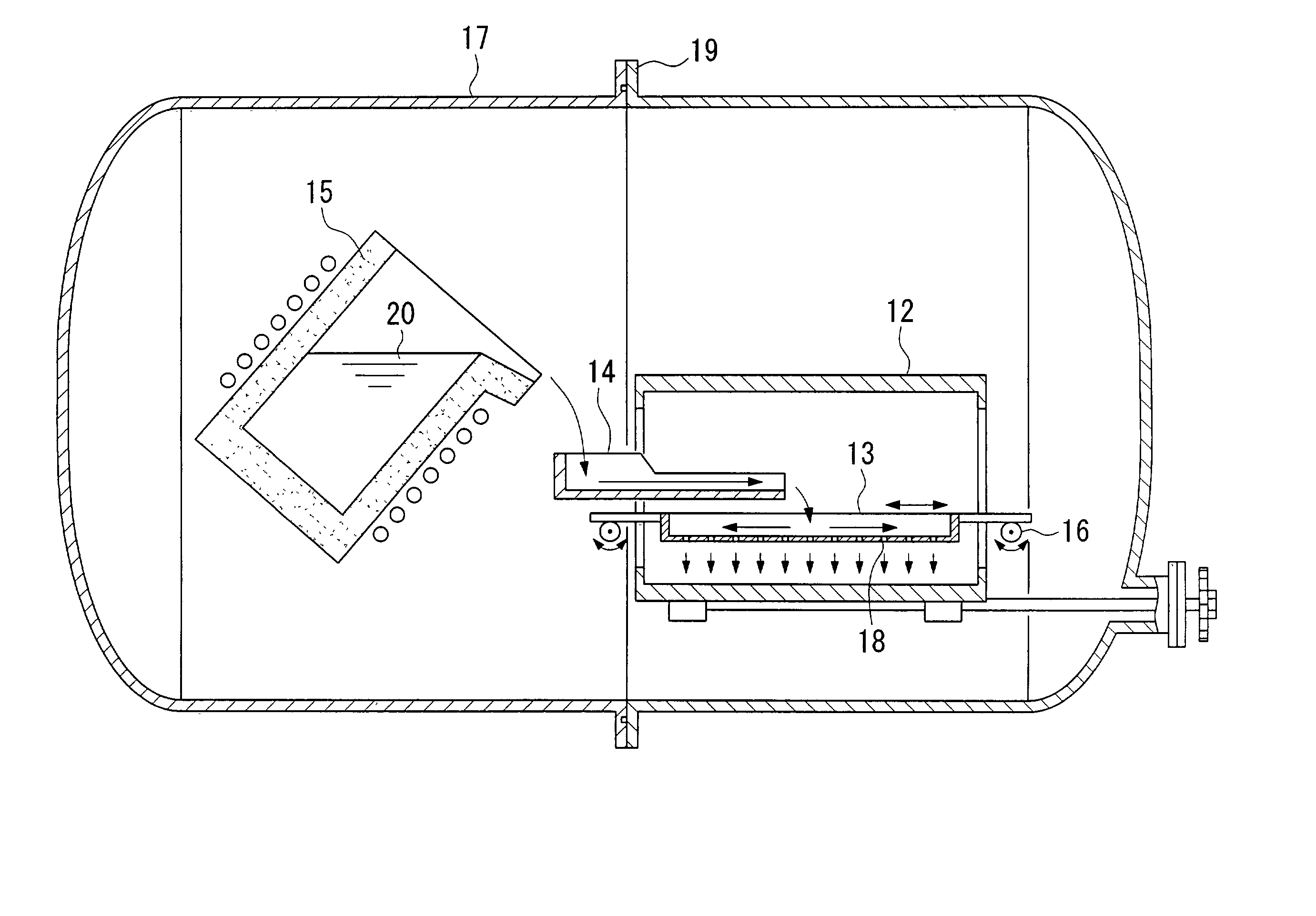
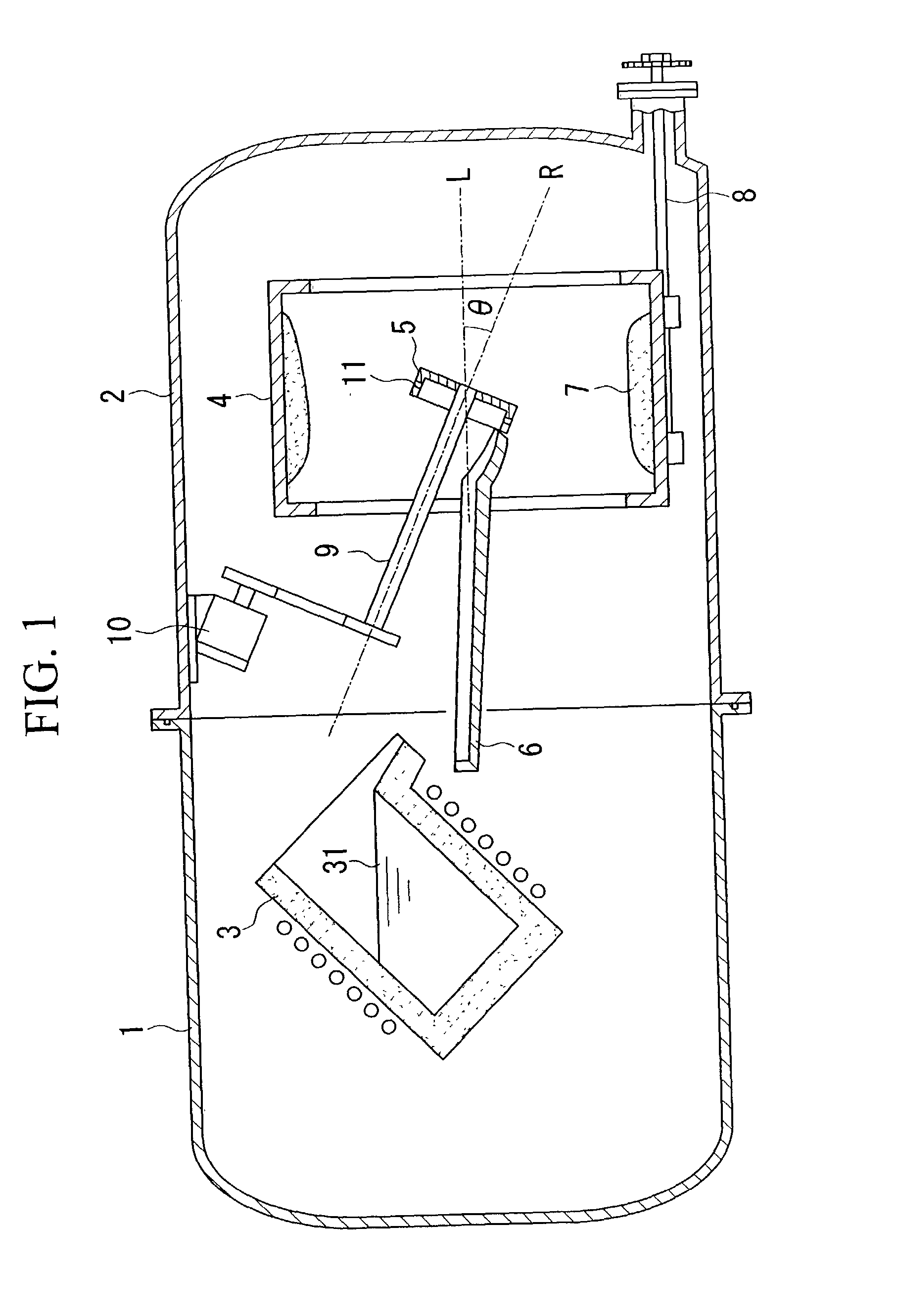
[0178] Elemental neodymium, elemental dysprosium, ferroboron, aluminum, and electrolytic iron were weighed and mixed so as to obtain the following composition: Nd: 12.6 at. % (28.0% by mass); Dy: 0.6 at. % (1.5% by mass); B: 6.0 at. % (1.0% by mass); Al: 0.7 at. % (0.30% by mass); and a balance of iron. The resulting mixture was melted in an alumina crucible in an argon gas atmosphere by use of a high-frequency induction melting furnace. The resulting molten mixture was subjected to casting by use of the centrifugal casting apparatus shown in FIG. 1.

[0179] The cylindrical mold 4 was of an inside diameter of 500 mm and a length of 500 mm. The container-like rotary body 5 was of an inside diameter of 250 mm, and eight hole portions 11 of a 2 mm diameter were formed in the sidewall thereof. The angle of inclination .theta. formed by the axis of rotation R of the container-like rotary body 5 and the axis of rotation L of the cylindrical mold was fixed to 25 degrees during casting.

[0180]...

example 2

[0190] In order to obtain a composition in which TRE is further decreased, elemental neodymium, ferroboron, aluminum, and electrolytic iron were weighed, mixed so as to have the following composition: Nd: 12.4 at. % (28.0% by mass); B: 5.9 at. % (1.0% by mass); Al: 0.7 at. % (0.30% by mass); and a balance of iron. Casting was performed by use of an apparatus similar to that used in Example 1 under the same conditions as those of Example 1.

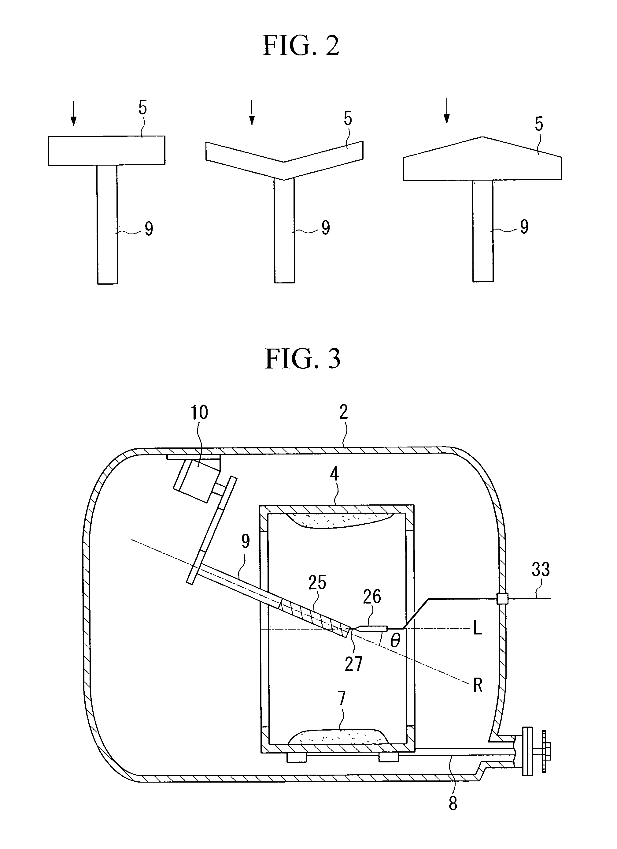
[0191] During casting, the container-like rotary body 5 was moved such that the angle of inclination .theta. formed by the axis of rotation R of the container-like rotary body 5 and the axis of rotation L of the cylindrical mold is varied continuously between 0 degree and 25 degrees. The average molten-material deposition rate was 0.004 cm / sec.

[0192] On the cross section of an ingot, the microstructure containing the dendritic .alpha.Fe phase occupied an area percentage of 3%, and crystal grains having an average diameter of 75 .mu.m as measured al...

example 3

[0193] In order to obtain a composition in which TRE is further decreased, elemental neodymium, ferroboron, and electrolytic iron were weighed and mixed so as to have the following composition: Nd: 11.6 at. %; B: 5.9 at. %; and a balance of iron. Casting was performed by use of an apparatus similar to that used in Example 1 under the same conditions as those of Example 1 except that the angle of inclination .theta. formed by the axis of rotation R of the container-like rotary body 5 and the axis of rotation L of the cylindrical mold was varied continuously between 0 degree and 25 degrees and that the average molten-material deposition rate was 0.003 cm / sec.

[0194] The thickness of an ingot was substantially uniform; specifically, an average of 6 mm. FIGS. 8 and 9 show back scatterd electron micrographs of a cross section of an ingot. FIG. 9 is a partially enlarged view of FIG. 8. FIG. 8 shows the generation of the gray T1 phase serving as the matrix phase, a small amount of dendritic...


PUM

PropertyMeasurementUnit
angle of inclinationaaaaaaaaaa
angleaaaaaaaaaa
deposition rateaaaaaaaaaa

Abstract

The present invention relates to a casting method which employs rapid solidification of metal, rare-earth metal or the like, as well as to a casting apparatus and a cast alloy. A centrifugal casting method includes the steps of pouring a molten material onto a rotary body; sprinkling the molten material by the effect of rotation of the rotary body; and causing the sprinkled molten material to be deposited and to solidify on the inner surface of a rotating cylindrical mold. The axis of rotation of the rotary body and the axis of rotation of the cylindrical mold are caused not to run parallel to each other. The centrifugal casting method can attain a decrease in average deposition rate. As a result, generation of the dendritic alphaFe phase or generation of a segregation phase of Mn or the like is suppressed, thereby realizing a high-performance R-T-B-type rare-earth magnet alloy.

Description

[0001] This application claims the benefit pursuant to 35 U.S.C. .sctn.119(e)(1) of U.S. Provisional Applications No. 60 / 234,350 filed Sep. 22, 2,000 and No. 60 / 263,239 filed Jan. 23, 2001.[0002] The present invention relates to a casting method which employs rapid solidification of metal, rare-earth metal, high-melting-point metal, nonmetal or the like, as well as to a casting apparatus and a cast alloy.[0003] In recent years, as peripheral equipment for personal computers--such as HDDs (hard disk drives)--AV equipment, household electric equipment, and the like have become lightweight, compact, and of higher performance, demand for sintered rare-earth magnets represented by Nd-based (neodymium-based) magnets has sharply increased. Typical alloys for such magnets are the Nd--Fe--B-type alloys, which additionally contain iron and boron and are typified by a composition Nd.sub.2Fe.sub.14B.[0004] In many of these rare-earth magnets, in order to improve magnetic properties, to enhance ...

Claims


Application Information

Patent Timeline
Patent Type & Authority Applications(United States)
IPC IPC(8): B22D13/02B22D13/10H01F1/057H01F41/02
CPCB22D13/02B22D13/023B22D13/107B82Y25/00H01F41/0273H01F1/0575H01F1/0577H01F1/0579H01F1/057
Inventor HASEGAWA, HIROSHIUTSUNOMIYA, MASAHIDEHOSONO, UREMUHIROSE, YOICHI
Owner TDK CORPARATION
Why Eureka
Try Eureka