

Manufacturing method of semiconductor device
a manufacturing method and semiconductor technology, applied in the field of manufacturing methods of semiconductor devices, can solve the problems of resist pattern flow due to heat, side wall warp, and warp on the side wall, and achieve the effect of reducing exposure energy, reducing the dimension of the lower layer, and obtaining the desired retreat amount of the resist relatively easily
- Summary
- Abstract
- Description
- Claims
- Application Information
AI Technical Summary
Benefits of technology
Problems solved by technology
Method used
Image

Examples
embodiment 1
[0077] In embodiment 1, a manufacturing method of a GOLD structured TFT having a gate electrode of double-layered structure, which has, compared to a second layer gate electrode, a first layer gate electrode of a thinner film thickness and a longer dimension in the channel direction, will be described with reference to FIG. 5.
[0078] First of all, a polycrystalline silicon film 202 of 50 nm in film thickness is formed on an insulative glass substrate 201 by laminating an amorphous silicon film of 53 nm in film thickness by means of a plasma CVD or a low pressure CVD and then subjecting the same to heat treatment. In this case, as the heat treatment method of the amorphous silicon film, heat treatment at 600.degree. C., for 24 hours by means of an annealing furnace, laser crystallization by means of laser power 200 mJ / cm.sup.2 or more or a combination of the heat treatment by means of an annealing furnace and the laser crystallization is available (refer to FIG. 5-A).
[0079] Next, a ga...
embodiment 2
[0092] Referring to FIG. 6, different from the first mode of carrying out the invention, another manufacturing method of a GOLD structured TFT having a double-layered gate electrode in which, compared to a second layer gate electrode, a first layer gate electrode is thinner in film thickness and longer in dimension of the channel direction will be described.
[0093] In embodiment 2, since the manufacturing steps shown in FIG. 6-A to FIG. 6-C are the same basically as the manufacturing steps shown in FIG. 5-A to FIG. 5-C of embodiment 1, detailed description thereof will be omitted herein. These manufacturing processes will be described just schematically below. Using a resist pattern 306a as a mask, successive dry etching processing is carried out by means of first step etching and second step etching to form a gate electrode having a first shape comprised of a first layer gate electrode film 304c and a second layer gate electrode film 305c. Further, an n-type impurity of high dose am...
example 1
[0103] Referring to FIG. 7-FIG. 12, embodiments of a manufacturing method of an active matrix type liquid crystal display device will be described in detail. In the following embodiments, as for a semiconductor layer that is the active layer of the TFT, an example will be given, in which not ordinary polycrystalline silicon film but crystalline silicon film, which is crystallized using a catalyst element (element for promoting crystallization of silicon), is adopted.
[0104] First of all, a first layer silicon nitride oxide film 402a is deposited 50 nm in film thickness and a second layer silicon nitride oxide film 402b is deposited 100 nm in film thickness, which have different composition ratio, respectively, on a glass substrate 401 by means of the plasma CVD to form a base film 402. As for the glass substrate 401 used in this example, a quartz glass, a barium borosilicate glass or an aluminum borosilicate glass or the like is available. Then, an amorphous silicon film 403a is depo...
PUM
| Property | Measurement | Unit |
|---|---|---|
| length | aaaaa | aaaaa |
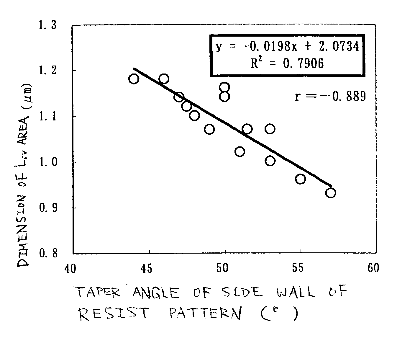
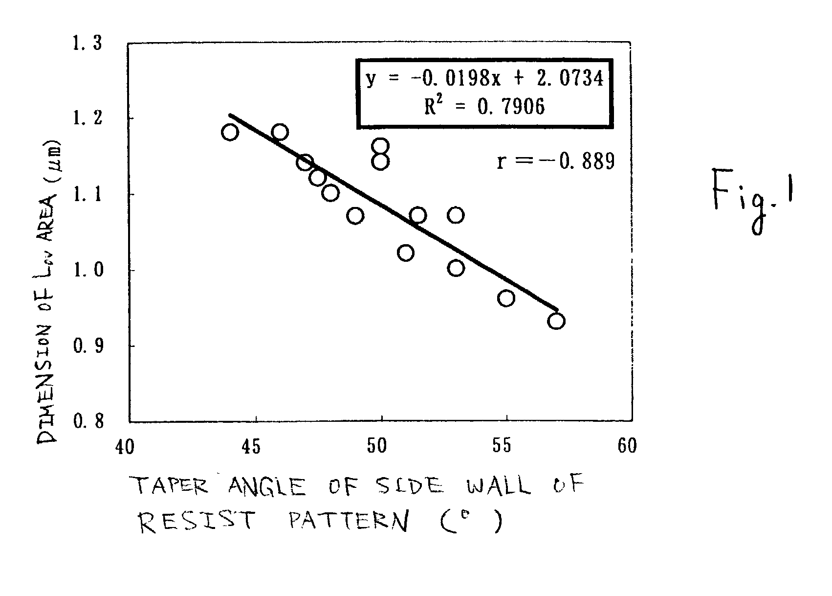
| taper angle | aaaaa | aaaaa |
| temperature | aaaaa | aaaaa |
Abstract
Description
Claims
Application Information