Removal of biofilm from surfaces

a biofilm and surface technology, applied in the field of biofilm, can solve the problems of large microbial contamination, inability to achieve satisfactory biofilm removal from four out of ten duwl systems studied, and high contaminating microorganisms, so as to achieve simple and more effective, less complex

Inactive Publication Date: 2003-07-03
COUGHLIN ROBERT W +3
View PDF7 Cites 59 Cited by
  • Summary
  • Abstract
  • Description
  • Claims
  • Application Information

AI Technical Summary

Benefits of technology

[0025] The present invention provides a far simpler and more effective method for removing biofilm, especially from the difficult-to-access inner wall of conduits. The present invention also provides improved compositions and methods for removing biofilm from the inner wall of conduits that are far simpler, less complex and more convenient than those heretofore known.

Problems solved by technology

The problems associated with biofilm in water lines in clinical dental systems are typical and illustrative of biofilm problems that occur in cleaning medical devices, cleaning conduits and processing apparatus in the food, water treatment and pharmaceutical industries, or in any industry that employs water.
Biofilm formation on the water-contacting surfaces of dental delivery units results in widespread microbial contamination.
It was later demonstrated, however, that the contamination is attributable to microbes sloughing from the biofilms that flourish on the walls of the DUWLs into the treatment-water flowing through the lumens of the DUWLs (Williams, et al., 1995).
(1999) combined continuous and periodic treatment using hypochlorite solution but, using this protocol, these workers were unable to achieve satisfactory biofilm removal from four out of ten DUWL systems studied.
The clinical problem with contaminated treatment-water is that the contaminating microbes can be highly enriched for both opportunistic and primary pathogenic bacteria (Shearer, 1996).
The presence of these pathogens presents two complications for the dental practitioner.
First, patients with actual or potential immune dysfunction, (e.g., AIDS patients, cancer patients, the elderly, diabetics and cystic fibrosis patients) are at increased risk of morbidity associated with infections caused by contaminated treatment-water.
Clearly dental treatment-water contamination can adversely impact both patient and care-giver.
Multiple treatments were able to control the bacterial level in the water but failed to remove the biofilm matrix on the wall of the tubing.
Although the potential pathological significance of biofilms that form on solid surfaces has been appreciated for at least a decade, little progress has been made in developing new technology for biofilm eradication.
Chemical agents sufficiently aggressive to completely destroy biofilm can also attack the underlying solid surface and cause costly destruction in expensive systems such as DUWSs.
No widely accepted rinse or irrigation has yet been found to replace the mechanical action of brushing as the best known means of controlling dental plaque.
Generally, it has been found that merely flushing DUWLs with water is inadequate to control microbial contamination.
The use of bleach solution is an approach recommended by at least one manufacturer (A-dec Corporation, 1995), although this procedure can cause aggressive corrosion of metal fittings and related system parts depending on water conditions such as pH, ionic strength and oxygen tension.

Method used


Image

  • Removal of biofilm from surfaces
  • Removal of biofilm from surfaces
  • Removal of biofilm from surfaces

Examples


example 1

Preparation of Bacterial Cultures

[0092] Sterile Difco Tripticase Soy Broth (TSB) (50 ml) was inoculated with Pseudomonas aeruginosa (ATCC 700829) (this bacterium is sometimes referred to herein as PA) using cells scraped from a frozen culture using sterile Pt loop. The TSB had been prepared with sterilized 18 megohm pure water. This starter culture was incubated in a 250 ml-flask at 30.degree. C. for 24 hr with shaking at 150 rpm. To prepare the culture employed to form biofilm on tubing walls, the 24-hr starter culture was added to 100 ml of (tenth strength) sterile TBS in a 250-ml flask until an OD of 0.1 was attained. This occurred after about 10 ml of 24-hr starter culture was added to the dilute sterile TSB.

example 2

Formation of Biofilm Inside Tubing

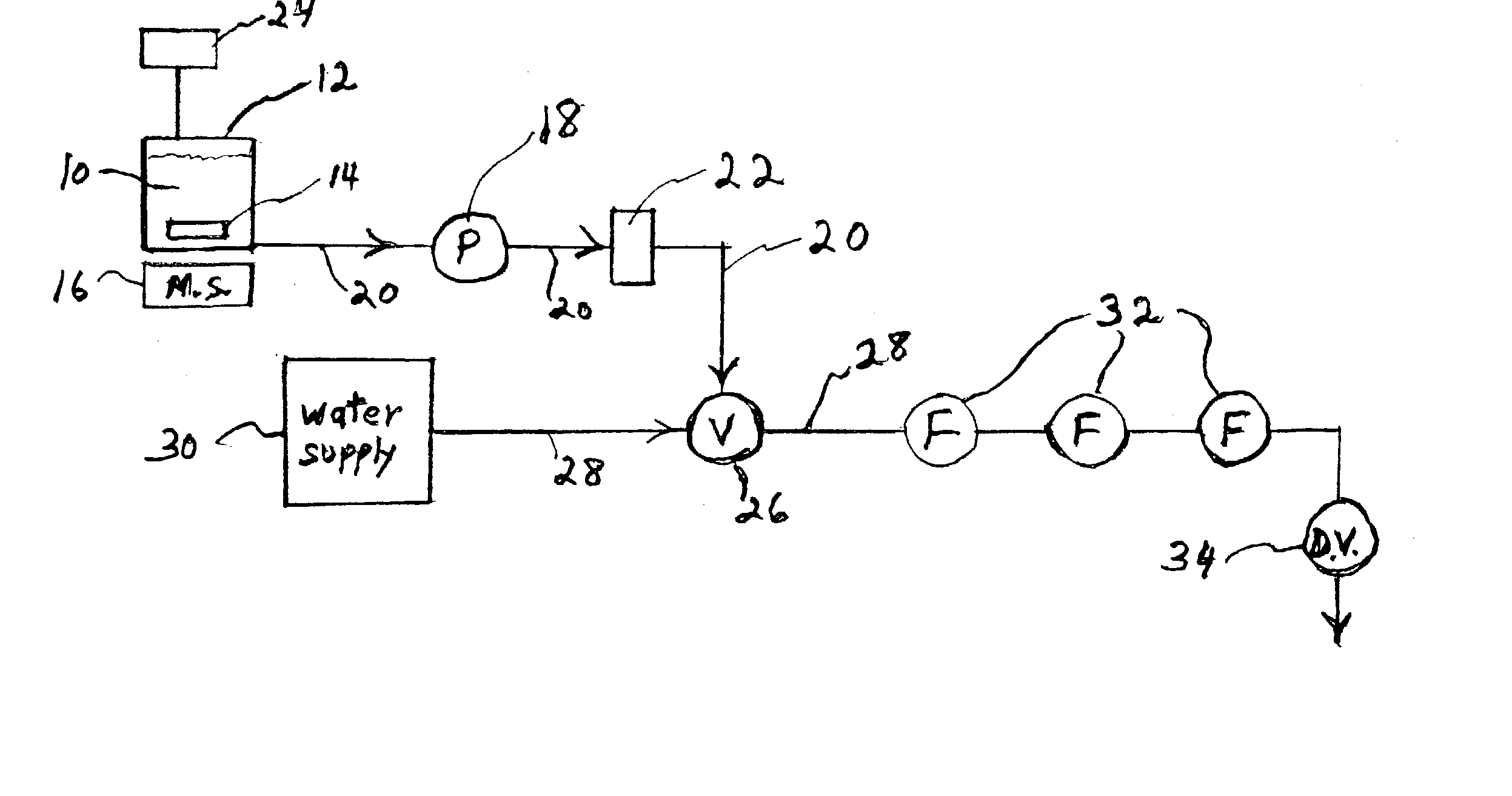
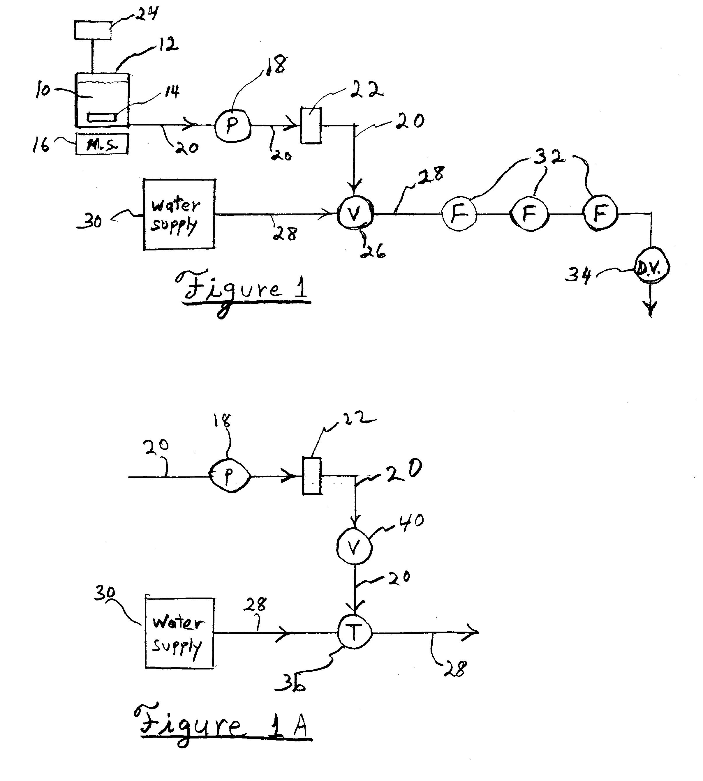
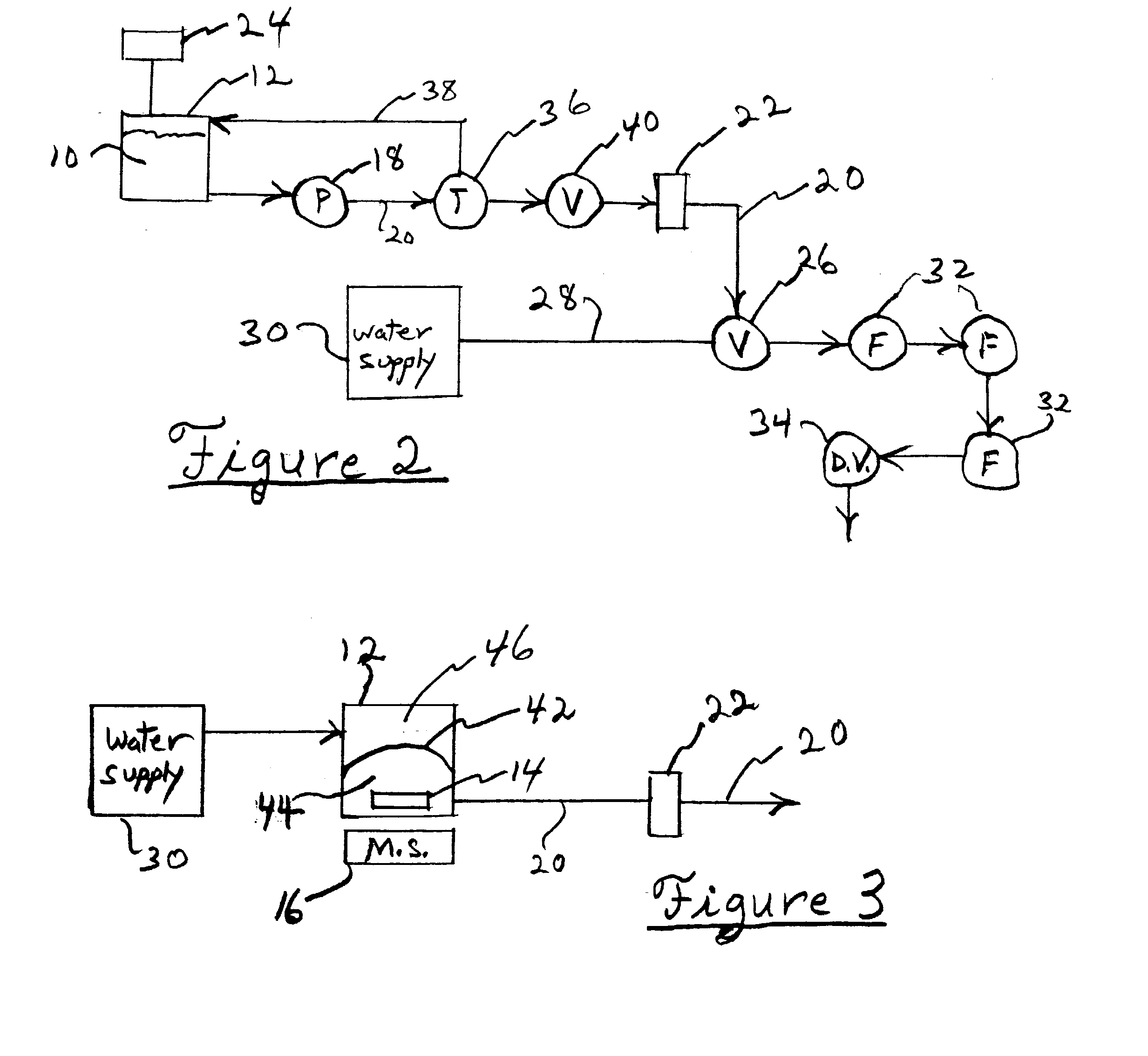
[0093] Biofilm-forming culture (100 ml prepared as described in Example 1) was re-circulated by a peristaltic pump from a reservoir through three, 18.75-inch lengths (designated I, II or III) of tubing in parallel, and returned to the reservoir. Three pump heads were used and the flow rate through each length of tubing was 150 ml / hr. The tubing [about 3 mm in outside diameter (o.d.) and about 1.5 mm in inside diameter (i.d.)] was clear polyurethane Durometer 90A obtained from A-dec, Inc. Newberg, Ore. This tubing is typically used as conduit for water in dental units (dental unit water lines, sometimes referred to as DUWLs). The reservoir was a 250-ml flask, which was continuously stirred magnetically and aerated by sparging with sterile-filtered air. Biofilm became established on the inner wall of the tubing by operating this apparatus at room temperature, under ambient lighting for seven days.

example 3

Preparation of Biofilm-Coated Tubing (BFCT) for Further Investigation

[0094] Each tubing length (designated Length I, Length II or Length III) of BFCT was removed from the re-circulation apparatus described in Example 2 and placed in a sterile petri dish. Working in a filtered laminar flow hood (Biosafety Level II), each BFCT Length was cut into four upstream segments (each 3.75 in long and designated A, B, C, D) for investigation of cleaning protocols using liquid suspensions of particles according to the present invention. Biofilm was assayed by a chemiluminescent method described more fully in subsequent examples. A fifth downstream segment (3.75 inches long) designated E was removed only from tubing length II for investigation of cleaning by a slurry protocol according to the present invention, and employing scanning electron microscopy (SEM) to assess the status of the biofilm before and after cleaning. Segment II-E was not used in experiments employing chemiluminescent measurem...


PUM

PropertyMeasurementUnit
densityaaaaaaaaaa
time periodaaaaaaaaaa
thicknessaaaaaaaaaa

Abstract

The disclosure encompasses composition, method and apparatus that provide improved and convenient removal of biofilm from surfaces. Surfaces cleaned according to the invention comprise the inner wall of conduits such as those employed in dental clinics, food and pharmaceutical manufacturing.

Description

PRIORITY CLAIM[0001] This application claims the benefit of Provisional Application No. 60 / 328,580 filed by the same inventive entity in the USPTO on Oct. 11, 2001.[0003] Biofilms are complex microbial communities embedded in a protective matrix that is largely a polysaccharide slime excreted by the microbes. Biofilms form spontaneously and deposit on surfaces in most aqueous environments. Many people can recall experience of a biofilm in the form of a slime layer on a stone plucked from a brook or as a film of plaque removed from their teeth by cleaning at a dentist's office. The matrix (sometimes called glycocalix) of a biofilm protects the organisms within from biocides, predation, dehydration and attack by immune systems (in the case of biofilms on plant or animal tissue). Biofilms are very frequently undesirable because they can include pathogenic microorganisms that are possible dangerous infectious agents. Undesirable biofilms form on implants or indwelling devices within the...

Claims


Application Information

Patent Timeline
Patent Type & Authority Applications(United States)
IPC IPC(8): A61B1/12A61L2/02A61L2/18B08B3/02B08B9/04B24C3/32B24C11/00C11D3/10C11D3/12C11D3/37C11D17/00
CPCA61B1/126C11D17/0013A61L2/186A61L2202/17B08B3/02B08B9/057B24C3/327B24C11/00C02F2303/20C11D3/10C11D3/122C11D3/1233C11D3/1266C11D3/37A61L2/02
Inventor COUGHLIN, ROBERT W.MAHMOUD, WAFAA M.DAVIS, EDWARD M.REDDY, HEATHER L.
Owner COUGHLIN ROBERT W
Why Eureka
Try Eureka