Process and device for forming ceramic coatings on metals and alloys, and coatings produced by this process

a technology of ceramic coatings and ceramic coatings, which is applied in the direction of electrolytic coatings, surface reaction electrolytic coatings, electrolytic coatings, etc., can solve the problems of difficult to remove defective layers, large external porous layer of low microhardness, and high cost, and achieve high physico-mechanical properties, low roughness, and high uniformity of thickness

Inactive Publication Date: 2003-10-09
KERONITE INT LTD
View PDF6 Cites 37 Cited by
  • Summary
  • Abstract
  • Description
  • Claims
  • Application Information

AI Technical Summary

Benefits of technology

0066] A considerable advantage of the process of embodiments of the present invention is the fact that it makes it possible to produce dense microcrystalline ceramic coatings of thickness up to 1501 / 4 m, preferably from 2 to 1501 / 4 m, and microhardness 500 to 2100 HV on metals in a relatively short time (from a few minutes to one hour).
0067] The coatings have low roughness, Ra 0.6 to 2.11 / 4 m, and a very thin external porous layer, comprising not more than 14% of the total thickness of the coating. This eliminates, or significantly reduces, the need for subsequent laborious finishing of the surface (FIG. 3).
0068] The coatings are characterised by high uniformity of thickness, even on articles of complex shape.
0069] The highly dispersed polycrystalline ceramic coatings consist of melted globules, up to several microns in size, firmly bonded to each other. This structure produces high physico-mechanical properties in the coatings, such as resistance to wear and corrosion, and dielectric strength. Furthermore, the addition to the electrolyte of solid nanopowders of a specific chemical composition provides for targeted changes in the structure, microhardness, strength and colour of the coatings, optimising the properties of the coatings for specific application conditions.
0070] Embodiments of the present invention enable a ceramic coating to be formed at a rate of 2 to 101 / 4 m / min, which considerably exceeds the rate of formation of hard ceramic coatings by known prior art processes.

Problems solved by technology

The coatings are characterised by a high degree of uniformity of thickness, low surface roughness and the virtual absence of an external porous layer, the removal of which usually involves considerable expense in conventional coating processes.
The main problem with this process is the formation of a considerable external porous layer of low microhardness and with numerous micro- and macro-defects (pores, micro-cracks, flaky patches).
If the article is of complex shape, with surfaces that are difficult for abrasive and diamond tools to reach, the problem of removing the defective layer becomes difficult to solve.
This limits the range of application of the process.
Other problems with the known process are the relatively low rate at which the coating forms and the high energy consumption.
It is not possible to increase the productivity of the oxidation process simply by raising the current density to higher than 20A / dm.sup.2, since the process then becomes an arc process rather than a spark one; and due to the appearance of strong local burn-through discharges, the whole coating becomes very porous and flaky and adhesion to the substrate deteriorates.
However, industrial frequency current is used in this process, which leads to the formation of a relatively thick external porous layer with high surface roughness and relatively high energy costs.
However, the pairs of powerful pulses alternate with unjustifiably long pauses, which leads to a low coating formation rate.
However, the use of positive pulses alone does not make it possible to produce good-quality coatings with high microhardness and wear resistance.
The problem with this process is the use of very short high-voltage positive pulses, which does not make it possible to create discharges of sufficient power.
This leads to low productivity of the process, and it is also extremely difficult to implement the proposed process technically for industrial purposes.

Method used


Image

  • Process and device for forming ceramic coatings on metals and alloys, and coatings produced by this process
  • Process and device for forming ceramic coatings on metals and alloys, and coatings produced by this process
  • Process and device for forming ceramic coatings on metals and alloys, and coatings produced by this process

Examples


example 2

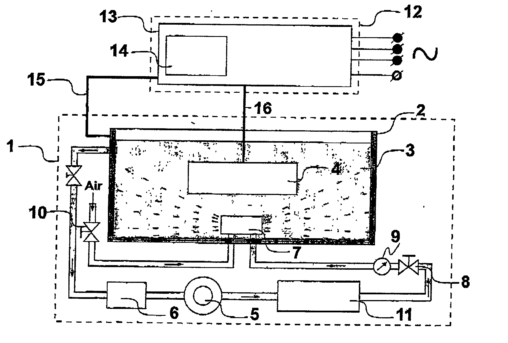
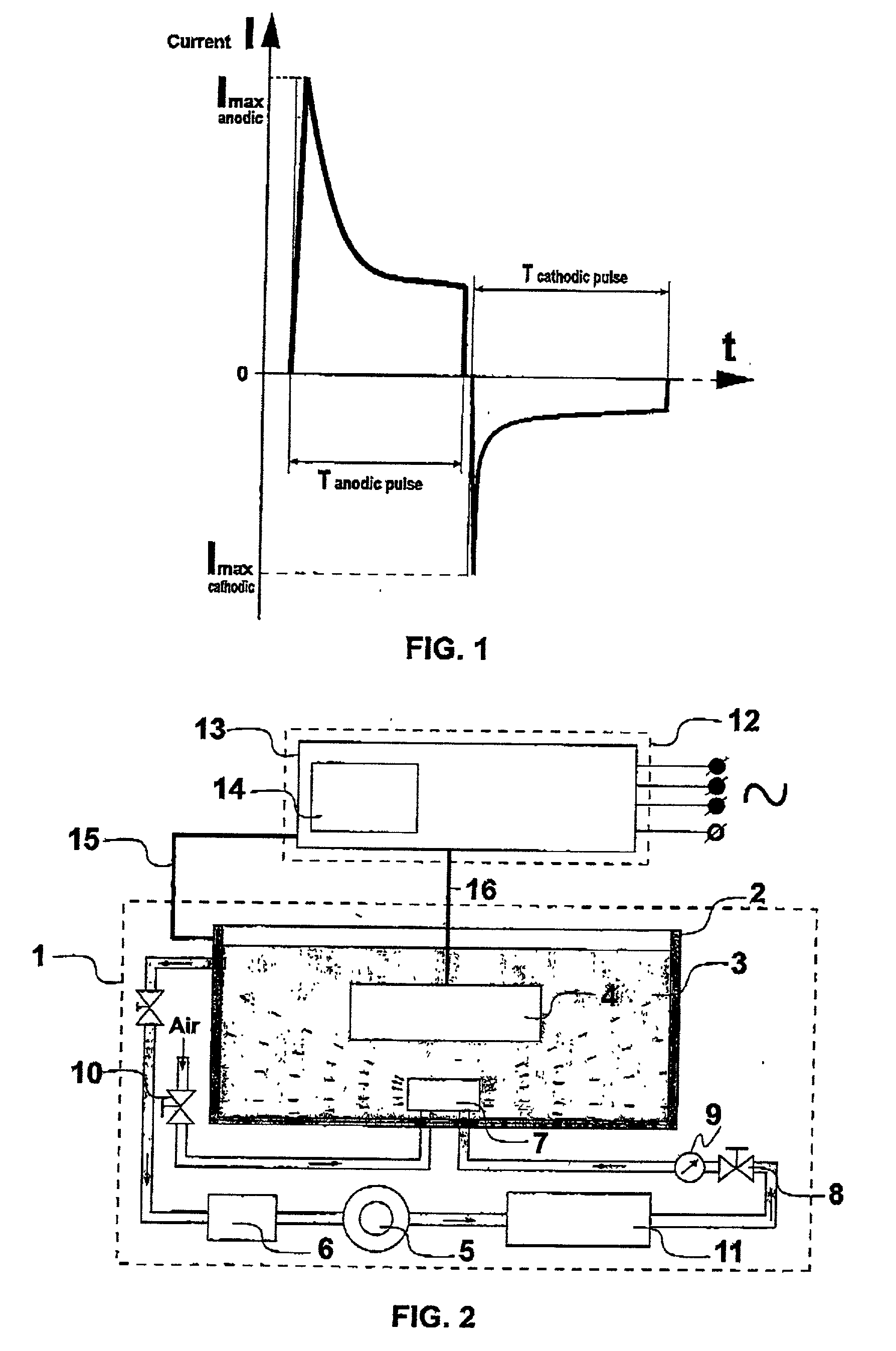
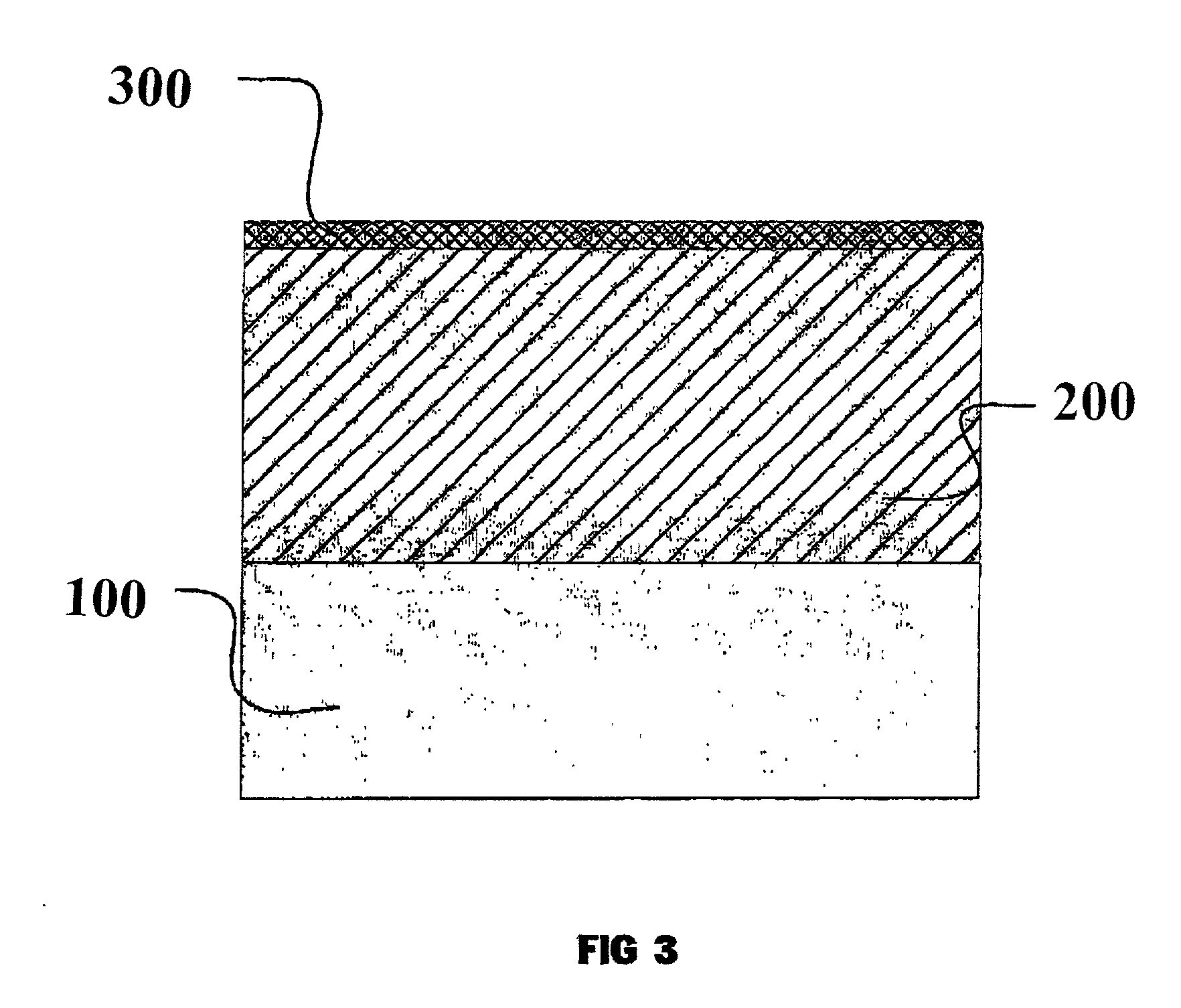
[0084] A specimen of magnesium alloy AZ91 was oxidised for two minutes in a phosphate-aluminate electrolyte to which 2 g / l of ultra-disperse Al.sub.2O.sub.3 powder with particle size 0.21 / 4 m was added. The temperature of the electrolyte was 25.degree. C., pH 12.5. Bipolar alternating electrical pulses of frequency 10,000 Hz were supplied to the bath in turn. The current density was 10A / dm.sup.2 and the final voltage (amplitude) was: anode 520V, cathode 240V. Acoustic vibrations were generated in the bath using an aerohydrodynamic generator. The pressure of the electrolyte at the input to the generator was 4.8 bars. The coating obtained was dense, of a white colour, overall thickness 20.+-.11 / 4 m, including an external porous layer of thickness 21 / 4 m. The roughness of the oxidised surface was Ra 0.81 / 4 m, the microhardness of the coating was 600 HV, and the porosity of the functional layer was 6%.

example 3

[0085] A specimen of titanium alloy Ti Al6 V4 was oxidised for seven minutes in a phosphate-borate electrolyte to which 2 g / l of ultra-disperse Al.sub.2O.sub.3 with particle size 0.21 / 4 m was added. The temperature of the electrolyte was 20.degree. C., pH 9. Bipolar alternating electrical pulses of frequency 1,000 Hz were supplied to the bath. The current density was 60A / dm.sup.2 and the final voltage (amplitude) was: anode 500V, cathode 180V. Acoustic vibrations were generated in the bath using an aerohydrodynamic generator. The pressure of the electrolyte at the input to the generator was 4.0 bars. The coating obtained was dense, of a bluish-grey colour, overall thickness 15.+-.11 / 4 m, including an external porous layer of thickness 21 / 4 m. The roughness of the oxidised surface was Ra 0.71 / 4 m, the microhardness of the coating was 750 HV, and the porosity of the functional layer was 2%.

example 4

[0086] A specimen of AlBemet alloy, containing 38% aluminium and 62% beryllium, was oxidised for 20 minutes in a phosphate-silicate electrolyte, pH 9, at temperature 30.degree. C. Bipolar electrical pulses of frequency 3,000 Hz were supplied to the bath. The current density was 35A / dm.sup.2 and the final voltage (amplitude) was: anode 850V, cathode 350V. Acoustic vibrations were generated in the bath using an aerohydrodynamic generator. The pressure of the electrolyte at the input to the generator was 4.5 bars. The coating obtained was dense, of a light grey colour, overall thickness 65.+-.21 / 4 m, including an external porous layer of thickness 81 / 4 m. The roughness of the oxidised surface was Ra 1.21 / 4 m, the microhardness of the coating was 900 HV, and the porosity of the functional layer was 5%.


PUM

PropertyMeasurementUnit
current densityaaaaaaaaaa
frequencyaaaaaaaaaa

Abstract

There is disclosed a process and apparatus for carrying out plasma electrolytic oxidation of metals and alloys, forming ceramic coatings on surfaces thereof at a rate of 2-10 microns per minute. The process comprises the use of high-frequency current pulses of a certain form and having a given frequency range, combined with the generation of acoustic vibrations in a sonic frequency range in the electrolyte, the frequency ranges of the current pulses and the acoustic vibrations being overlapping. The process makes it possible to introduce ultra-disperse powders into the electrolyte, with the acoustic vibrations helping to form a stable hydrosol, and to create coatings with set properties. The process makes it possible to produce dense hard microcrystalline ceramic coatings of thickness up to 150 microns. The coatings are characterised by reduced specific thickness of an external porous layer (less than 14% of the total coating thickness) and low roughness of the oxidised surface, Ra 0.6-2.1 microns.

Description

[0001] Priority of UK Patent Application Serial No. 0207193.4 filed in the name of Isle Coat Limited on 27 Mar. 2002, incorporated herein by reference, is hereby claimed.[0002] Not applicableREFERENCE TO A "MICROFICHE APPENDIX"[0003] Not applicable[0004] The invention relates to the field of applying protective coatings, and in particular to plasma discharge, for example plasma-electrolytic oxidation, coating of articles made of metals and alloys. This process makes it possible rapidly and efficiently to form wear-resistant, corrosion-resistant, heat-resistant, dielectric uniformly-coloured ceramic coatings on the surfaces of these articles.[0005] The coatings are characterised by a high degree of uniformity of thickness, low surface roughness and the virtual absence of an external porous layer, the removal of which usually involves considerable expense in conventional coating processes.[0006] The process for producing the coatings and the device for implementing the process, descri...

Claims


Application Information

Patent Timeline
Patent Type & Authority Applications(United States)
IPC IPC(8): C25D5/18C25D5/20C25D11/02C25D15/00
CPCC25D5/18C25D5/20C25D11/005C25D11/026C25D11/024C25D15/00C25D5/611C25D5/617C25D5/627
Inventor SHATROV, ALEXANDER SERGEEVICHSAMSONOV, VICTOR IOSIFOVICH
Owner KERONITE INT LTD
Why Eureka
Try Eureka