Method of fabricating fuel cells and membrane electrode assemblies

a technology of membrane electrodes and fuel cells, which is applied in the direction of cell components, final product manufacturing, sustainable manufacturing/processing, etc., can solve the problems of reducing the reliability of fuel cell products, increasing the complexity of the process, and difficult assembly, so as to reduce production costs and costs.

Inactive Publication Date: 2004-03-18
NAT RES COUNCIL OF CANADA
View PDF19 Cites 116 Cited by
  • Summary
  • Abstract
  • Description
  • Claims
  • Application Information

AI Technical Summary

Benefits of technology

0023] The present invention overcomes the limitations of conventional fuel cell fabrication processes by enabling fuel cells and MEAs to be fabricated in a continuous process without assembly. The method minimizes production costs and costs of non-essential materials. In accorda...

Problems solved by technology

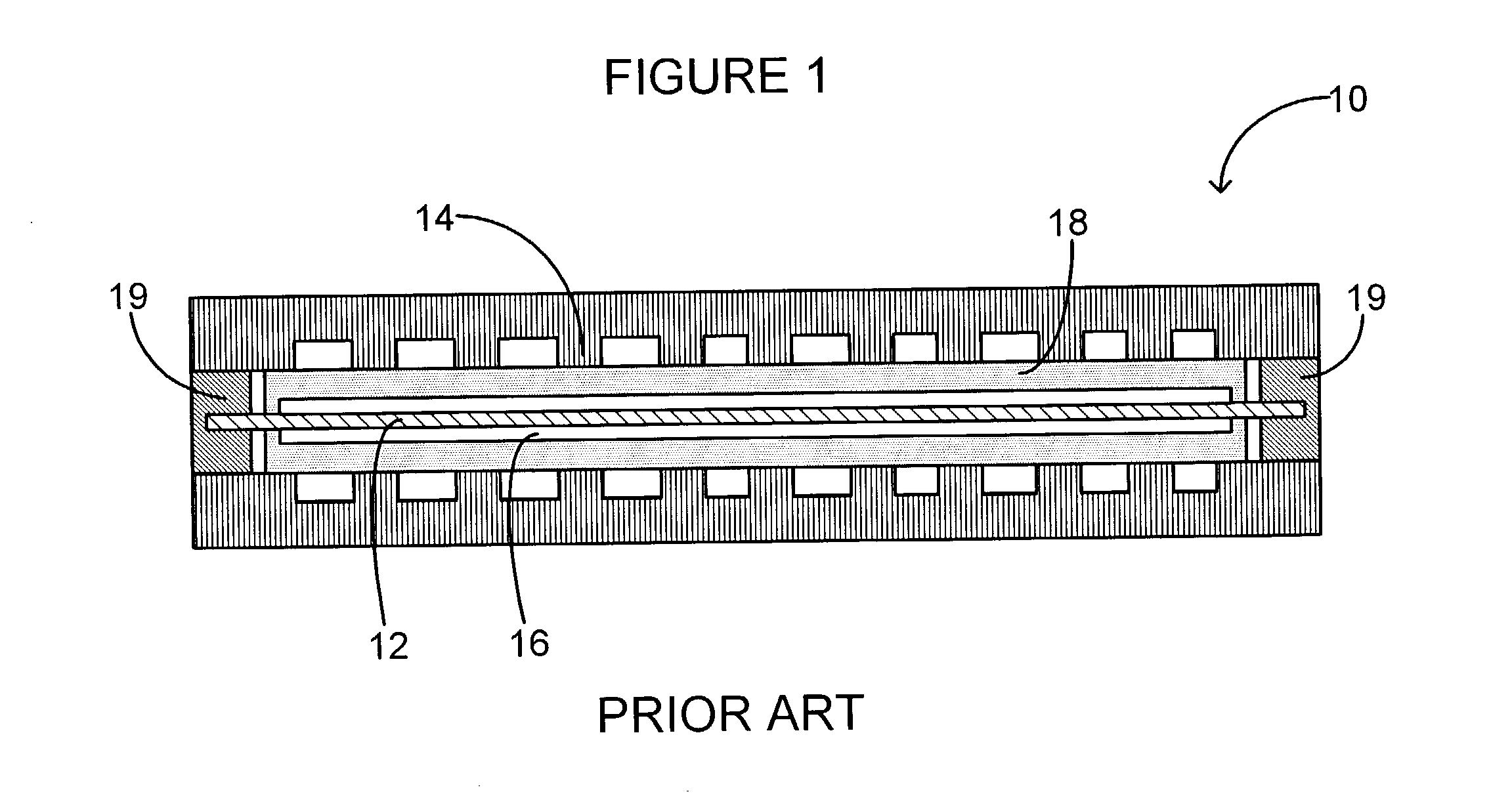
This assembly is difficult since many of the component parts are not rigid and require complex sealing regimes which are prone to failure.
The assembly process increases the complexity and reduces the reliability of fuel cell products.
Particular problems arise in the fabrication of micro fuel cells.
Most micro fuel cell fabrication processes employ traditional serial machining techniques, which are expensive to miniaturize, or MEMS techniques which are inherently batch processes and require expensive vacuum based steps.
These processes dramatically increase the cost of the fuel cell system and make competition with established solutions like lithium ion batteries unlikely.
Dong, however, focuses on the manufacture of electrochemical fuel cell strata or plates in which are formed flow field channels and does not describe the formation of an integrated fuel cell having current collectors directly deposited on a membrane substrate.
Assembly: As component parts become smaller, the...

Method used


Image

  • Method of fabricating fuel cells and membrane electrode assemblies
  • Method of fabricating fuel cells and membrane electrode assemblies
  • Method of fabricating fuel cells and membrane electrode assemblies

Examples


Embodiment Construction

[0079] The following examples will further illustrate the invention in greater detail, although it will be appreciated that the invention is not limited to the specific examples.

[0080] Membrane formation

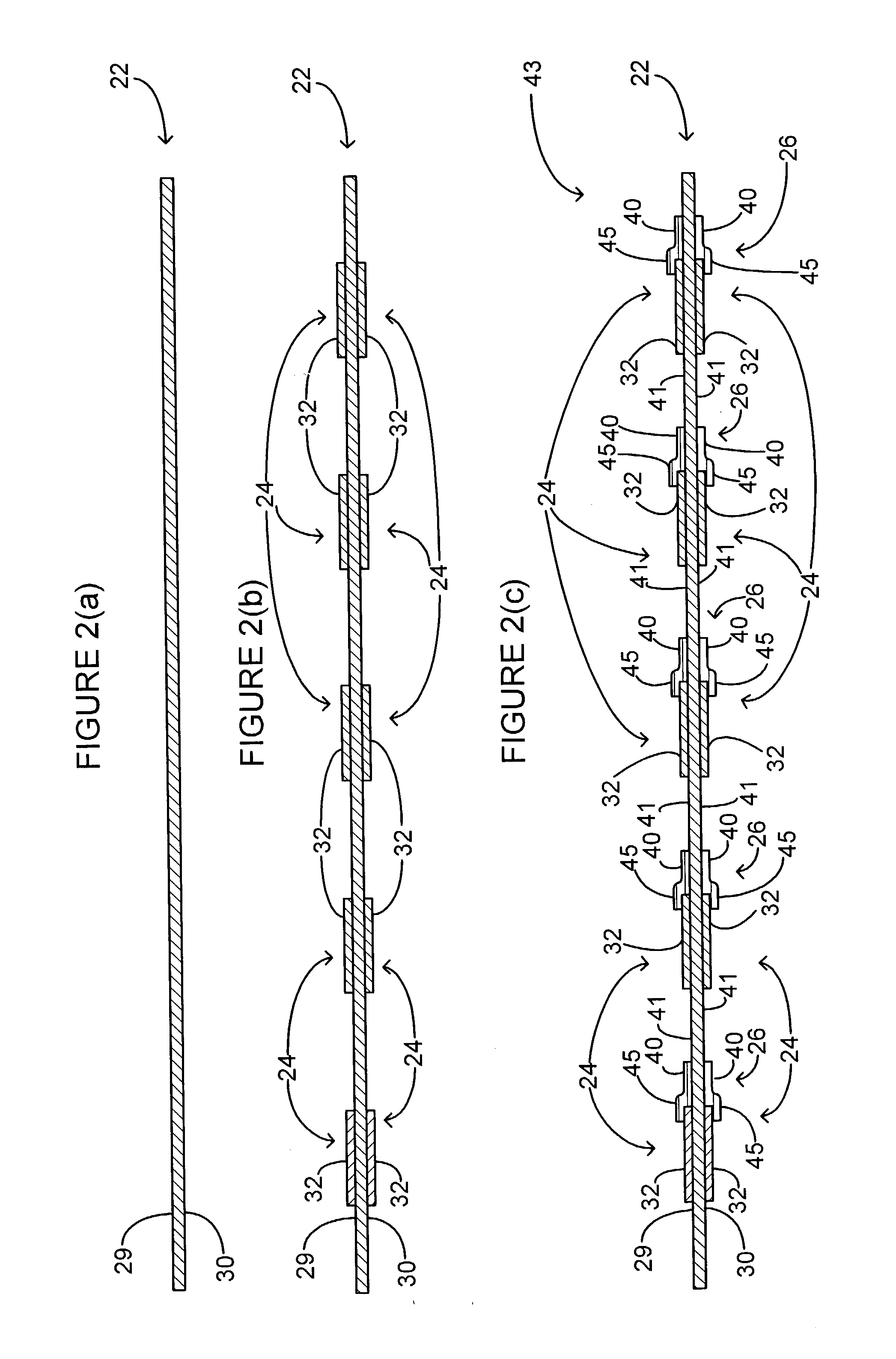
[0081] Both porous glass and Teflon.RTM. supported Nafion.RTM. membranes 22 have been researched. Both provide the mechanical support necessary to create dimensionally stable membranes 22. As described below, Nafion.RTM. ionomer or resin is applied to the porous glass or Teflon substrate, through a droplet or spray, or the porous substrate is immersed in Nafion.RTM. ionomer. Several coats are generally required to create a membrane without pinholes.

[0082] Glass substrates may exhibit superior performance because they are hydrophilic, and thus absorb the ionomer better. Dipping appears to yield better performance than dropping or spraying, especially with the glass substrate. Nafion.RTM. saturation can be reached in four dipping operations instead of nine dropping or spraying operatio...


PUM


Abstract

The application relates to a method of fabricating micro fuel cells and membrane electrode assemblies by thin film deposition techniques using a dimensionally stable proton exchange membrane as a substrate. The application also relates to membrane electrode assemblies and fuel cells fabricated in accordance with the method. The method includes the steps of successively depositing catalyst, current collector and flow management layers on the membrane substrate in predetermined patterns. Since the fuel cell is formed layer by layer, the need for assembly and sealing of discrete components is avoided. The method improves the contact resistance between the current collectors and catalyst layers and reduce ohmic losses, thereby avoiding the need for end plates or other compressive elements. This in turn reduces the overall thickness of the manufactured fuel cell. Since the fuel cell layers are optionally flexible, the devices may be fabricated using a continuous roller process or other automated means. The method minimizes production costs and costs of non-essential materials and is particularly suitable for low power battery replacement applications.

Description

REFERENCE TO RELATED APPLICATION[0001] This application claims the benefit of U.S. provisional patent application No. 60 / 410,001 filed Sep. 12, 2002.[0002] This application relates to a method of fabricating micro fuel cells and membrane electrode assemblies by thin film deposition techniques using a dimensionally stable proton exchange membrane as a substrate. The application also relates to membrane electrode assemblies and fuel cells fabricated in accordance with the method.[0003] Fuel cells are electrochemical devices that convert the chemical energy of a fuel (e.g. hydrogen or hydrocarbons) directly to electrical energy. They offer an environmentally friendly means to generate power with high efficiencies. They are modular in design and flexible with respect to size and fuel requirements. In general, a fuel cell functions by combining hydrogen and oxygen to form water, and the use of an electrode-electrolyte assembly ensures that this reaction is carried out electrochemically, ...

Claims


Application Information

Patent Timeline
IPC IPC(8): H01M4/86H01M4/88H01M4/92H01M8/02H01M8/10H01M8/24
CPCH01M4/8605H01M4/8825H01M4/92H01M4/926Y02E60/521H01M8/0271H01M8/0297H01M8/1004H01M8/241H01M8/0247Y02E60/50Y02P70/50H01M8/0258H01M8/2404H01M8/2457
Inventor STANLEY, KEVIN G.CZYZEWSKA, EVA K.VANDERHOEK, THOMAS P. K.WU, Q. M. JONATHANWONG, TERRANCE Y. H.
Owner NAT RES COUNCIL OF CANADA
Why Eureka
Try Eureka