Method of treating digested sludge

a technology of digested sludge and sludge, which is applied in the direction of sludge treatment by oxidation, water/sewage treatment by oxidation, and separation processes, etc. it can solve the problems of increasing sludge use, large space and cost, and the need for storing digested sludge on landfill sites, etc., to facilitate mechanical dewatering, facilitate drying, and good filtering effect of sludg

Inactive Publication Date: 2005-01-06
KEMIRA KEMI AB
View PDF8 Cites 50 Cited by
  • Summary
  • Abstract
  • Description
  • Claims
  • Application Information

AI Technical Summary

Benefits of technology

A further advantage of the invention is the good filterability of the sludge in dewatering. The reason is not quite clear but will probably, in addition to the effect of the acid treatment and the oxidising treatment of the sludge, also be due to a favourable effect of the trivalent iron phosphate precipitated in oxidation. It is assumed for excellent reasons that the precipitated trivalent iron phosphate owing to its particle size and structure has a favourable effect as a filtering aid in dewatering. Thus, in the invention it has been noted that, instead of a sticky sludge which is extremely difficult to dewater according to prior-art technique, a sludge which is easy to dewater is provided according to the invention, forming a pulverulent, non-sticky product, which can easily be dried by itself in ambient air.
After the treatment with an oxidiser, the sludge is dewatered. Dewatering preferably occurs at the same pH as that of the sludge in the treatment with oxidiser, i.e. pH 1-5. Optionally, a certain adjustment of the pH of the sludge can be made in order to neutralise it, i.e. to about pH 7, but a special alkaline treatment of the sludge in order to alkaline it is not made according to the invention. This means that the pH of the sludge in dewatering is at most 7 according to the present invention.
Dewatering can take place in a single step, but is preferably divided into predewatering and final dewatering. Predewatering occurs preferably in a mechanical predewatering device, such as a centrifuge or a rotary screen. Also the final dewatering (which may

Problems solved by technology

Depositing the digested sludge on landfill sites requires, however, large spaces and is costly.
Use of digested sludge as fertiliser is preferred, but this use has been increasingly questioned since the sludge contains heavy metals and other undesirable substances.
Reducing the amount of sludge by providing a high solids content of the digested sludge is difficult and has so far been achieved only at a high cost by a combination of mechanical dewatering and drying.
A further problem in treatment of digested sludge from wastewater purif

Method used


Image

  • Method of treating digested sludge
  • Method of treating digested sludge

Examples


example 1

Digested sludge was treated according to the invention by acid treatment, treatment with an oxidiser (hydrogen peroxide) and dewatering. The treatment took place at different temperatures. Then the contents of the following bacteria were determined: a) coliform 37° C., b) thermotolerant coliform, c) presumptive Escherichia coli, d) Clostridium perifringens, and e) salmonella.

In parallel the same determination was made on a sample of the same digested sludge that had not been treated according to the invention, but only heated to 70° C. for 30 min at pH 6.85. Moreover the bacterial content was determined in a blank of the digested sludge, i.e. a sample that had not been subjected to any treatment at all. The results are stated in Table 1. The Table states the sample marking kg 100% hydrogen peroxide / temp, ° C., for 30 min / pH. The values in the Table relate to the number of colony-forming units per ml of sludge having a solids content of 2.5% (cfu / ml)

TABLE 1Sample markingColiform...

example 2

The solids content (TS=dry solids) from two dewatering devices is compared on the one hand after treatment according to the invention by acid treatment and treatment with an oxidiser (hydrogen peroxide) and, on the other hand, without treatment according to the invention.

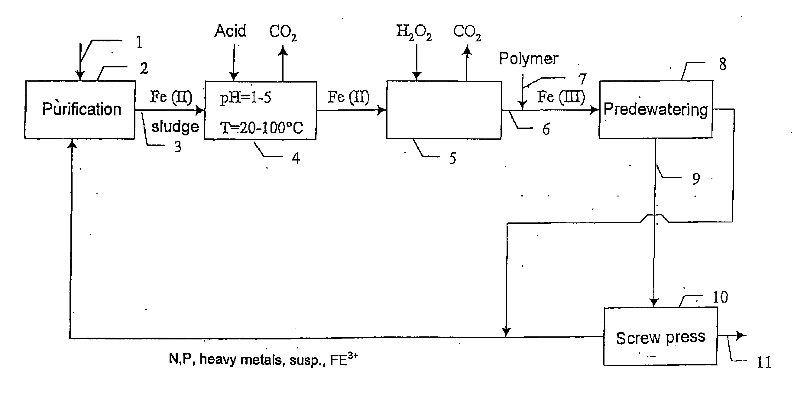
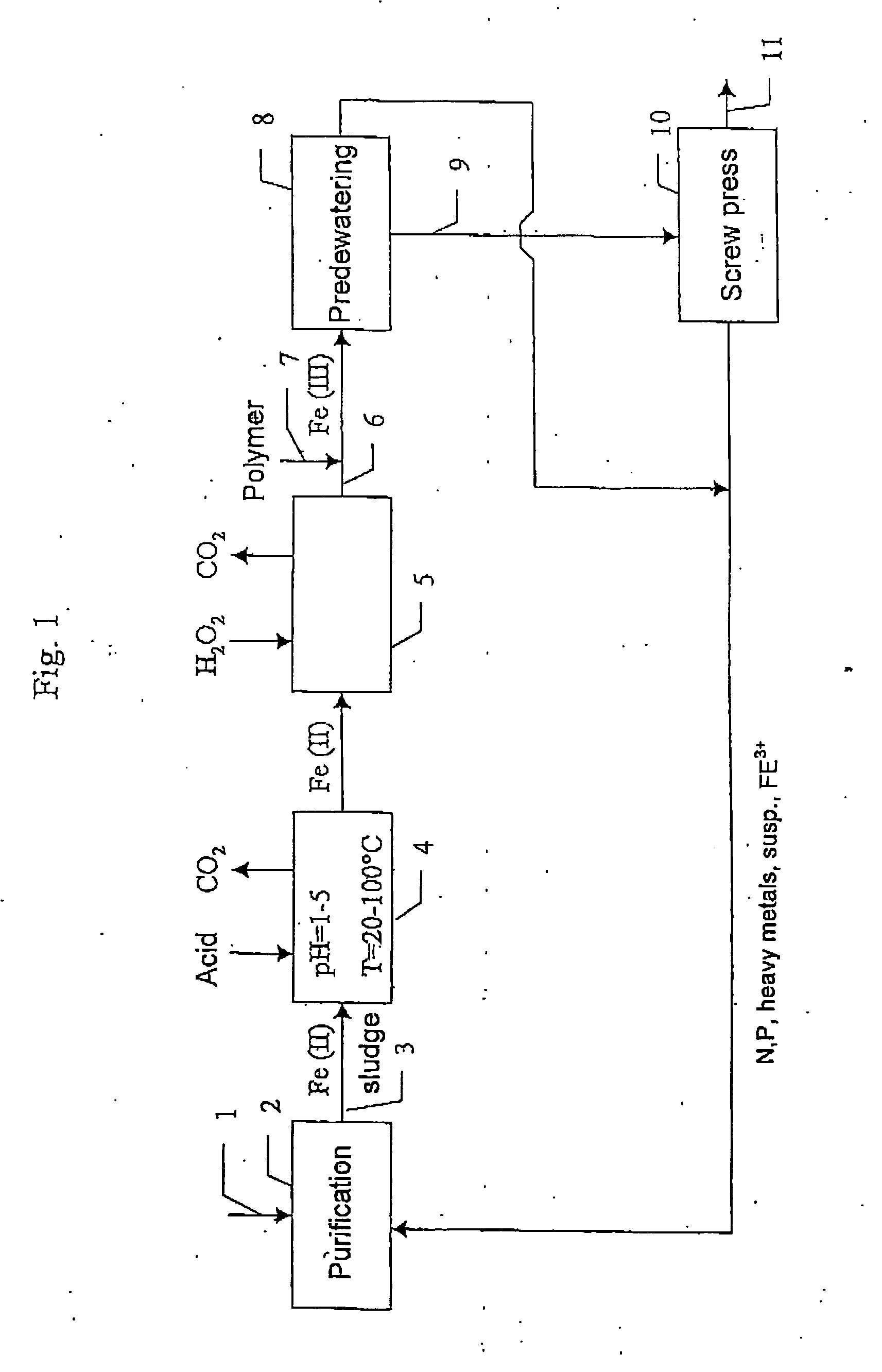
The sludge (digested sludge) contains at the inlet to the acid treatment and at the inlet to the dewatering devices 3% TS flocculated with polymer. The dewatering devices comprise a centrifuge, in which the sludge has a retention time of less than 1 min, and after that a screw press which is preceded by a dewatering drum. The screw press applies a pressure of 50 bar and the retention time of the sludge in the screw press is 15-30 min. In the dewatering drum, the sludge is dewatered to a TS content of 10-15% and is then fed to the screw press, the TS content being further increased. The results are stated in Table 2.

TABLE 2CentrifugeScrew pressTSUntreatedH2SO4: 360 kg / tonne TSUntreatedH2SO4: 350contentH2O2: 30 k...

example 3

The digested sludge was treated according to the invention by acid treatment, treatment with an oxidiser (hydrogen peroxide) and dewatering using a screw press. The following results were obtained at different temperatures.

TABLE 3HydrogenDry solidsTemperatureperoxideafter dewatering(° C.)(g / kg TS)pH(%)251003.63730100339701003.547

As is evident from the results, the treatment according to the invention gave a clearly increased TS content with an increased temperature.


PUM

PropertyMeasurementUnit
Temperatureaaaaaaaaaa
Weightaaaaaaaaaa
Weightaaaaaaaaaa

Abstract

A method of treating, in wastewater purification, sludge containing organic matter, divalent iron and phosphorus, in which the sludge that is treated is made to contain dissolved iron and phosphorus at a molar ratio Fe:P of above 1:1, the sludge is treated at 0-100° C. with an acid at a pH of 1-5 for dissolution of divalent iron and phosphorus from the sludge, the sludge is supplied with an oxidiser selected from hydrogen peroxide and percompounds, wherein divalent iron is oxidised by Fenton's reaction to trivalent iron, and (i) trivalent iron is precipitated as trivalent iron phosphate (ii) free radicals with a deodorisation and sanitation effect are formed by Fenton's reaction, the sludge is then dewatered at a pH of at most 7, and the aqueous solution obtained in dewatering is recirculated to the wastewater purification.

Description

FIELD OF THE INVENTION The present invention relates to a method of treating sludge. More specifically, the invention relates to a method of treating, in wastewater purification, sludge obtained from sewage works. The invention is especially useful in treatment of sludge from municipal sewage works and will therefore be described below with reference thereto. However, the invention is not limited to treatment of sludge from municipal sewage works, but is also applicable in treatment of sludge from other types of sewage works, such as sewage works for purification of industrial wastewater. BACKGROUND ART The water that is purified in municipal sewage works is collected from a large number of sources. It usually comprises the accumulated flows of domestic wastewater, surface water, partly purified industrial wastewater and rain water. In wastewater purification, first large objects that have got into the wastewater are removed. Moreover removal is made of particles and gravel, and f...

Claims


Application Information

Patent Timeline
IPC IPC(8): C02F1/56C02F1/66C02F1/72C02F11/06C02F11/12C02F11/14C02F11/18
CPCC02F1/56C02F1/66C02F1/722C02F11/06C02F11/121C02F11/14Y10S210/916C02F2101/105C02F2101/203C02F2301/046C02F2303/04C02F2305/026Y10S210/906C02F11/18
Inventor KARLSSON, GORANKARSSON, INGEMARPETTERSSON, LENNARTRECKTENWALD, MICHAEL
Owner KEMIRA KEMI AB
Why Eureka
Try Eureka