Eureka AIR delivers breakthrough ideas for toughest innovation challenges, trusted by R&D personnel around the world.

Photoelectrolysis of water using proton exchange membranes

a proton exchange membrane and photoelectrolysis technology, applied in the field of photoelectrolysis, can solve the problems of low photoelectrode efficiency, additional hindrance in current design of photoelectrodes, poor stability, etc., and achieve the effect of eliminating water surface tension, improving efficiency and performance stability, and not incurring energy losses

Active Publication Date: 2005-01-13
GAS TECH INST
View PDF5 Cites 17 Cited by
  • Summary
  • Abstract
  • Description
  • Claims
  • Application Information

AI Technical Summary

Benefits of technology

Accordingly, it is one object of this invention to provide a photoelectrolysis cell having improved efficiency and performance stability over convention photoelectrolysis cells.
It is another object of this invention to provide a photoelectrolysis cell which enables the transmission of sunlight to the photoelectrode catalyst surface without incurring the energy losses incurred in conventional photoelectrolysis cells.
It is yet a further object of this invention to provide a photoelectrolysis cell suitable for splitting water into hydrogen and oxygen, which eliminates the water surface tension responsible for hindering the escape of the hydrogen and oxygen gases from the catalyst surface encountered in conventional photoelectrolysis cells.
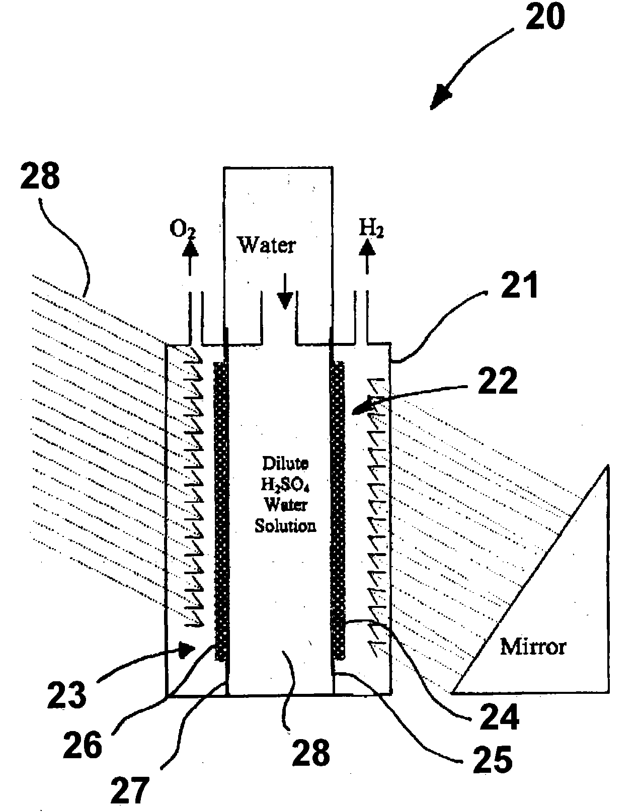
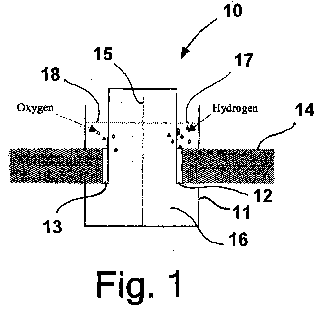
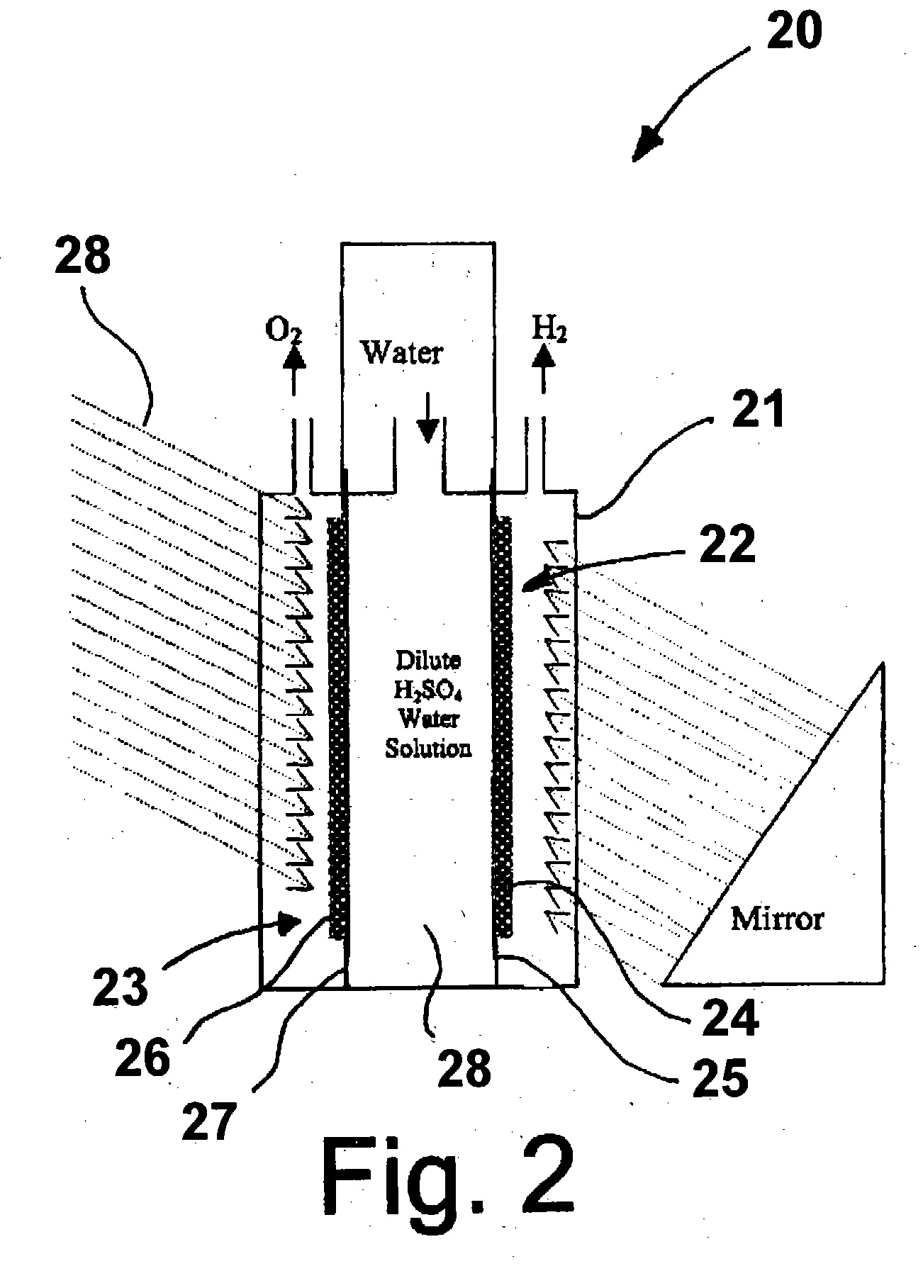
These and other objects of this invention are addressed by a photoelectrochemical cell comprising a light transmissive enclosure, a semiconductor photoanode and a semiconductor photocathode disposed within the light transmissive enclosure, and an electrolytic solution disposed entirely between the semiconductor photoanode and the semiconductor photocathode. Because the electrolytic solution employed in the photoelectrochemical cell is limited to a volume disposed between the photoanode and the photocathode (collectively referred to herein as “photoelectrodes”), the sunlight is able to directly shine on the catalyst surfaces of the photoelectrodes to produce hydrogen and oxygen. Thus, this invention eliminates the solar energy losses due to water (electrolyte) sorption; and because there is no thick water (electrolyte) layer between the sunlight and the catalyst surfaces as in conventional photoelectrochemical cells, the product gases, hydrogen and / or oxygen, are able to leave the catalyst surface easily without any restriction imposed by water surface tension. That is, the three-phase (gas, solid catalyst and liquid electrolyte) area is optimized to increase the solar energy efficiency.
This is accomplished by employment of a photoelectrode assembly in which, the photo electro-catalysts are deposited onto a proton exchange membrane, such as NAFION, a perfluorosulfonic acid polymer available from DuPont. In this application, the proton exchange membrane performs a multitude of functions including gas separation, water containment, proton exchanger and water transporter. The ionomer of the proton exchange membrane in the catalyst layer acts as a capillary channel to transport water to the catalyst surface and as an electron conductor to transport electrons between the two photoelectrodes. In addition, this fully hydrophilic ionomer helps to distribute water to the catalyst surface without blocking the incoming solar energy.

Problems solved by technology

The hindrances to practical applications of the system include the poor stability and low efficiency of the photoelectrode due to photoelectrochemical reactions involving photon-electron transfer and recombination, redox exchange and surface corrosion.
The current design of photo electrodes is an additional hindrance to the development of improved photoelectrochemical systems because the semiconductors employed therein are fabricated on conductive substrates.
With this type of design, there is no way to reduce the thickness of the electrolyte layer and eliminate the surface tension that acts as an inhibitor to the release of product gases because the reactant water and electrolyte must be transported to the front of the electrode.

Method used


Image

  • Photoelectrolysis of water using proton exchange membranes
  • Photoelectrolysis of water using proton exchange membranes
  • Photoelectrolysis of water using proton exchange membranes

Examples


example 1

A photoelectrode in accordance with one embodiment of this invention is produced by dissolving hydrogen hexachloroplatinate (IV) (Aldrich) in water as a 100 ml 1% (W / W) solution. 0.2 g of TiO2 (Rutile) (Aldrich) is mixed into the solution [Pt:TiO2 (mole ratio)=1:1]. The solution is titrated with 1% NaBH4 (0.1 g NaBH4) (Aldrich). 0.1 g XC 72R carbon black, available from Cabot Corporation, Alpharetta, Ga., is added to the solution, which is then stirred well. The resulting suspension is filtered and washed until there are no chloride ions in the powder. The powder is then dried at 450° C. for about 2 hours. The dried powder is then ground and mixed with isopropanol and water with 20% NAFION (DuPont) thereby forming an ink. The ink is applied to a NAFION proton exchange membrane by any suitable coating technique, resulting in the formation of a photoanode. In a similar fashion, a photocathode can be produced using a p-type semiconductor instead of n-TiO2.

example 2

In this example, rutile type TiO2 is treated with TiCl4 solution. The TiCl4-modified TiO2 is sintered at 450° C. to produce a Ti-rich TiO2 (n-type) semiconductor powder. The powder is then mixed with isopropanol, 10% by weight XC-72R carbon black, and 20% by weight NAFION emulsion to form an ink solution. The ink is applied to the NAFION membrane by the decal method or other suitable coating techniques, resulting in formation of a photoanode. The photocathode is made from sintering TiO2 in a sulfur vapor environment at 450° C. The TiO2 powder is mixed with 1% by weight sulfur powder, which mixture is then sintered for about two hours at 450° C. The sintered mixture is then ground to mix with carbon black and NAFION as previously described.

example 3

In this example, a photoelectrode is produced as before with the exception that the 10%. by weight carbon black and 20% by weight NAFION are replaced by sulfonated polyaniline, i.e. Polyaniline-campphorsulfonic acid (PANI-CSA0.5). Polyaniline powder is mixed with campphorsulfonic acid to form PANI-CSA0.5, which is then dissolved in m-cresol. The resulting solution is then added to the TiO2 powder to form an ink comprising 70% by weight semiconductor catalyst and 30% by weight PANI-CSA0.5.


PUM

PropertyMeasurementUnit
semiconductoraaaaaaaaaa
band gapaaaaaaaaaa
electrically conductiveaaaaaaaaaa

Abstract

A photoelectrochemical cell which includes a light transmissive enclosure, a semiconductor photoanode disposed within the light transmissive enclosure, a semiconductor photocathode disposed within the light transmissive enclosure, and an electrolytic solution disposed entirely between the semiconductor photoanode and the semiconductor photocathode. This is achieved by the use of semiconductor photoelectrodes (photoanodes and photocathodes) which include a proton exchange membrane having an electrolyte facing surface in contact with the electrolytic solution and a light transmissive wall facing surface, and having a photo electro-catalyst disposed on the light transmissive wall facing surface.

Description

BACKGROUND OF THE INVENTION 1. Field of the Invention This invention relates to a method and apparatus for producing hydrogen and oxygen from water using photoelectrolysis. More particularly, this invention relates to a method and apparatus for photoelectrolysis of water to produce hydrogen and oxygen using sunlight illumination. 2. Description of Related Art Photoelectrochemistry is the study of the interaction of light (in particular, radiation in the “sunlight” region, about 87 to 308 kJ / mole or about 0.9 to about 3.2 eV per photon) with electronic flow and chemical reactions at the electrode surfaces in electrochemical cells. The radiation involved in this process has considerable energy and can be used for the direct production of electricity and the splitting of water into hydrogen and oxygen, referred to as photoelectrolysis. However, to be practical, efficient and inexpensive systems utilizing readily available materials must be devised for the conversion process. The hi...

Claims


Application Information

Patent Timeline
Patent Type & Authority Applications(United States)
IPC IPC(8): B23H3/04B23H5/10B23H7/22C25B9/23C25B11/00C25C7/02C25D17/00C25D17/10C25F7/00H01L31/00H01MH01M6/14H01M6/30
CPCC25B1/003Y02E10/542H01G9/2031Y02P20/133C25B1/55
Inventor FAN, QINBAI
Owner GAS TECH INST
Why Eureka
Eureka Blog
Learn More