Impedimetric biosensor and its use for rapid detection of bacterial pathogens in solution

a biosensor and impedimetric technology, applied in the direction of liquid/fluent solid measurement, instruments, electrochemical variables, etc., can solve the problems of inconvenient monitoring on-site, high cost, and high cost of construction, and achieve the effect of reliable and inexpensive construction

Inactive Publication Date: 2005-03-17
BOARD OF TRUSTEES OPERATING MICHIGAN STATE UNIV
View PDF13 Cites 76 Cited by
  • Summary
  • Abstract
  • Description
  • Claims
  • Application Information

AI Technical Summary

Benefits of technology

[0019] It is therefore an object of the present invention to provide a handheld device for the detection and ultimately identification of microorganisms in large bulk solutions. In

Problems solved by technology

In North America, HUS is the most common cause of acute kidney failure in children, who are particularly susceptible to this complication.
The PCR method is extremely sensitive but requires pure samples and hours of processing along with expertise in molecular biology (Meng et al., J. Food Microbiol.
These test methods, however, are completed in a microbiology laboratory and are not suitable for on-site monitoring.
Detection techniques for laboratory use cannot adequately serve the needs of health inspectors and monitoring agents in the field.
The systems are cos

Method used


Image

  • Impedimetric biosensor and its use for rapid detection of bacterial pathogens in solution
  • Impedimetric biosensor and its use for rapid detection of bacterial pathogens in solution
  • Impedimetric biosensor and its use for rapid detection of bacterial pathogens in solution

Examples


example 1

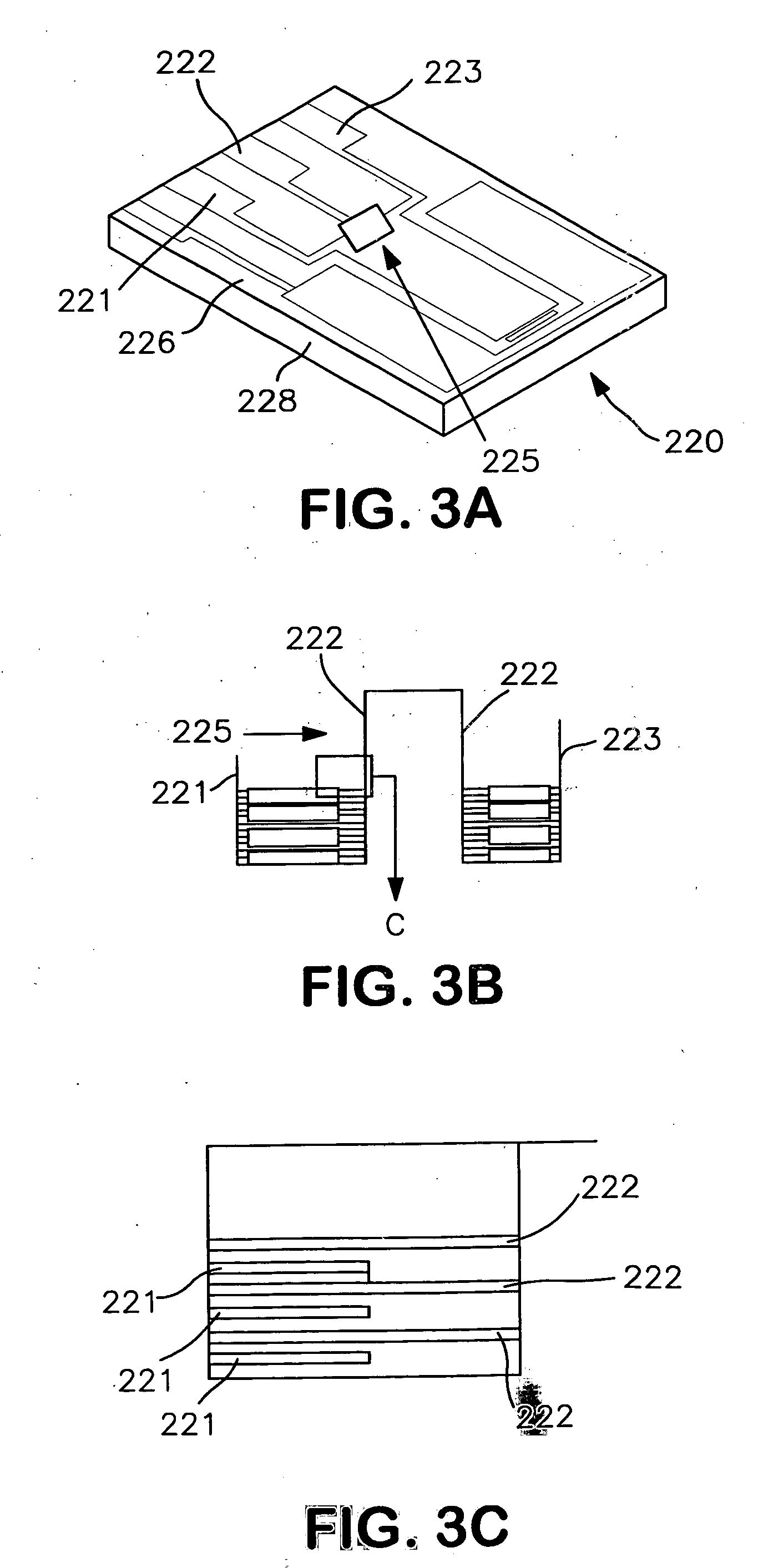
[0108] A biosensor is constructed as follows. A 4 inch (100 mm) diameter silicon wafer with 100 crystal orientation serves as the foundation. Then 2 μm of silicon oxide is grown over the silicon to act as an insulator. Next, photoresist (PR) is spun onto the wafer which is then exposed to UV radiation through a photomask containing the electrode pattern. Afterwards, the PR is developed in the pattern of the photomask.

[0109] Next, 30 nm of titanium followed by 50 nm of gold is deposited onto the wafer to form an interdigitated electrode structure, followed by removal of the PR. The wafer is then diced into 8 mm×12 mm chips.

[0110] Antibodies are attached to the silicon surface of the chips as follows. The silicon surface is cleaned by immersing the chip into a mixture of hydrochloric acid and methanol for 30 minutes, and then in sulfuric acid for 30 minutes, followed by rinsing in distilled H2O. The chip is then immersed in a silanizing solution of 3-mercaptomethyldimethylethoxysila...

example 2

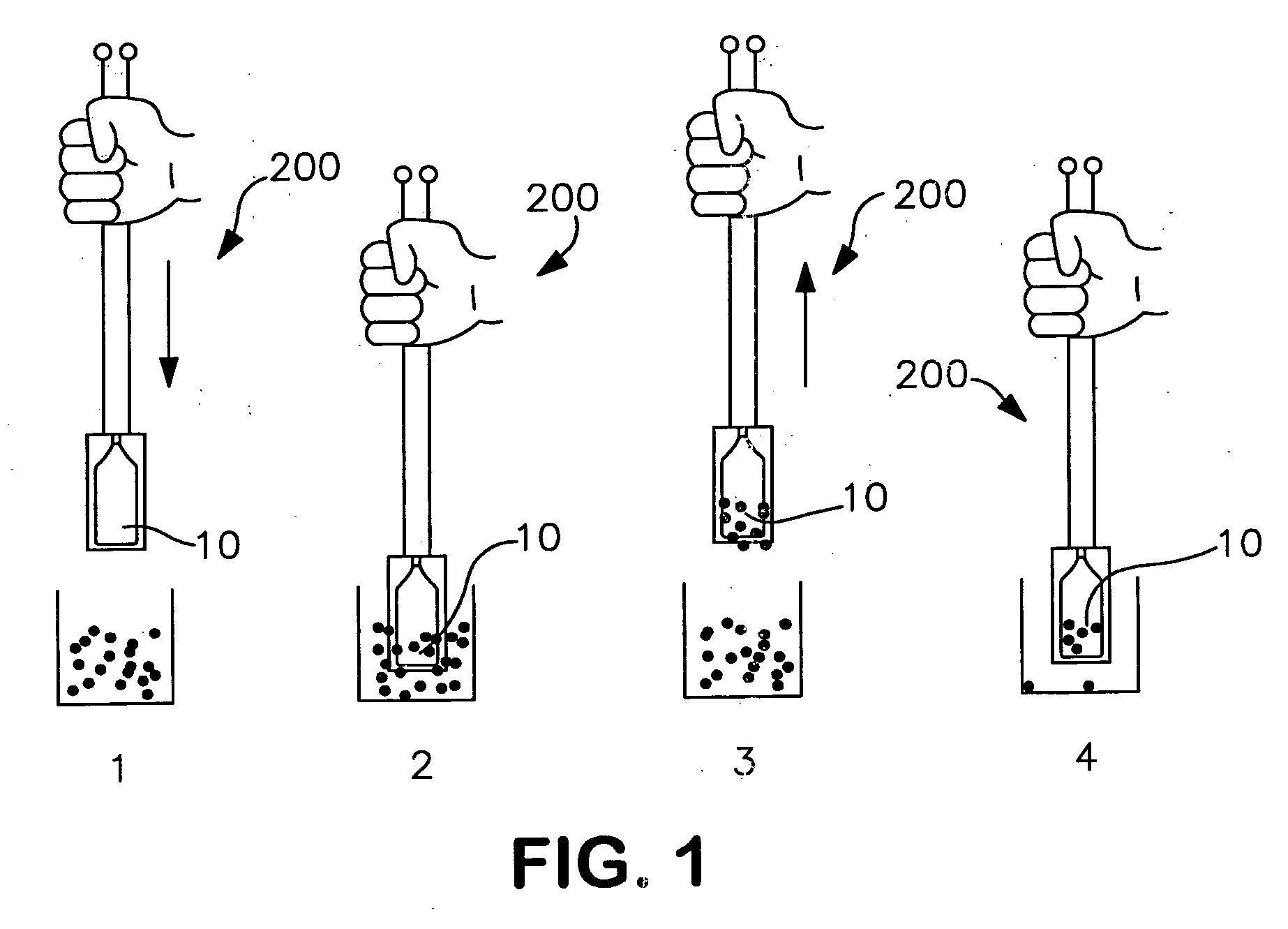
[0112] A prototype apparatus comprising a biosensor was fabricated and tested for ability to detect E. coli O157:H7 in a large sample volume.

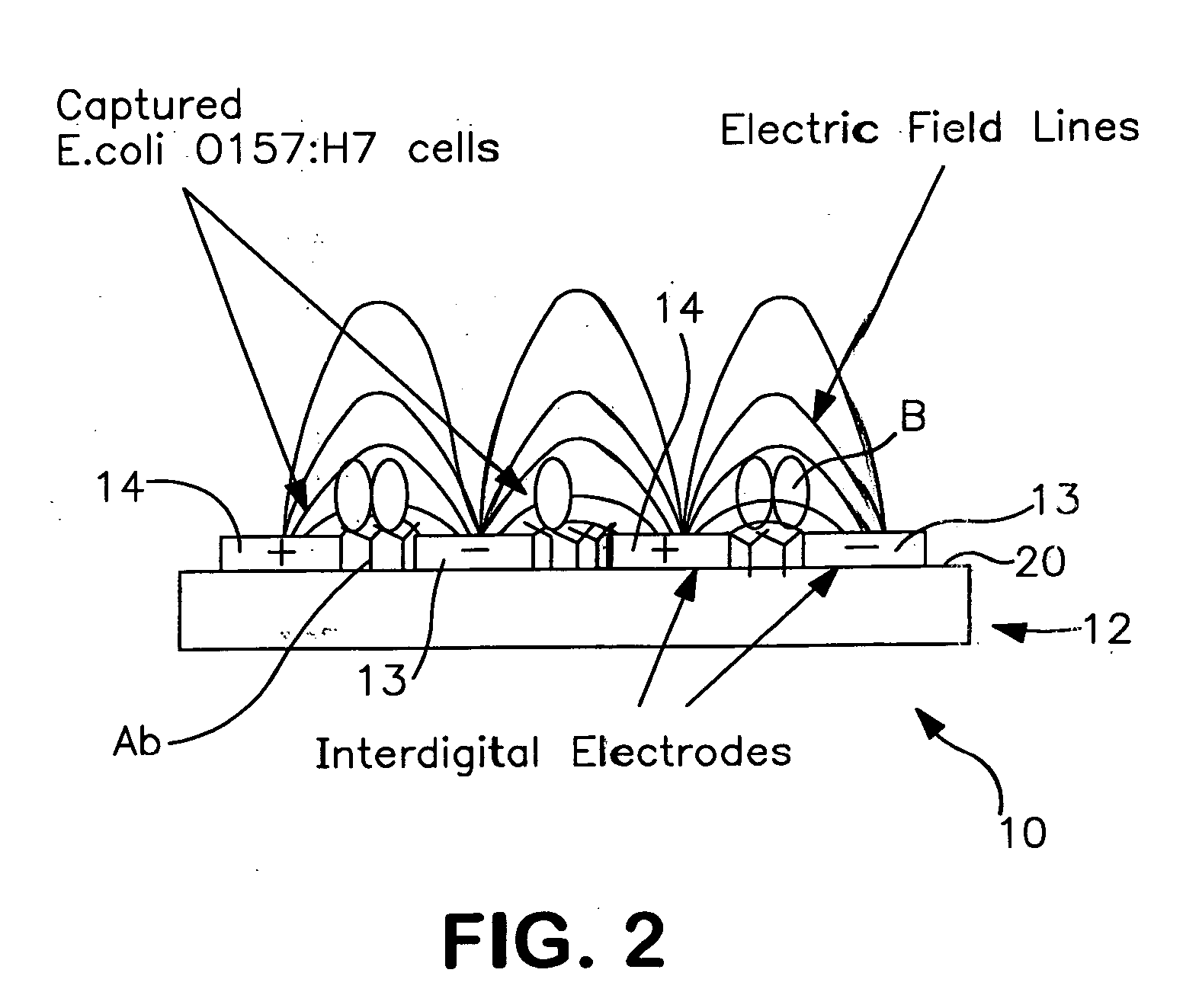
[0113] The biosensor was fabricated from a 100 Silicon wafer with a 2 μm layer of SiO2 as an insulating layer. The biosensor active area contained interdigital gold electrodes deposited over the SiO2 using photolithographic processing methods. Analyte specific antibodies were immobilized to the SiO2 in between the electrodes creating a biological sensing surface. Using impedance spectroscopy, the impedance across the interdigital electrodes was measured after immersing the biosensor in solution. Bacteria cells present in solution attached to antibodies and became tethered to the biosensor surface. Immobilized bacteria cells changed the dielectric constant and thus the capacitance, and the resistance of the media between the electrodes thereby causing a change in measured impedance. The biosensor was able to discriminate between different cellu...


PUM

PropertyMeasurementUnit
Lengthaaaaaaaaaa
Sizeaaaaaaaaaa
Widthaaaaaaaaaa

Abstract

A method and device for the rapid detection of microorganisms by detection of a change of impedance as a result of the microorganism being bound between interdigitated electrodes is described. In particular, the present invention relates to a handheld device to be used for the detection and, in many instances, the identification of the microorganism.

Description

CROSS-REFERENCE TO RELATED APPLICATION [0001] This applications claims priority to Provisional Application Ser. No. 60 / 490,105, filed Jul. 25, 2003.STATEMENT REGARDING FEDERALLY SPONSORED RESEARCH OR DEVELOPMENT [0002] The present invention was supported in part by United States Department of Agriculture Grant No. 00.38420.8839. The U.S. government has certain rights in the present invention.REFERENCE TO A “COMPUTER LISTING APPENDIX SUBMITTED ON A COMPACT DISC”[0003] Not Applicable. BACKGROUND OF THE INVENTION [0004] (1) Field of the Invention [0005] The present invention relates to a method and device for the rapid detection of microorganisms by detection of a change of impedance as a result of the microorganism being bound between spaced apart electrodes. In particular, the present invention relates to a device to be used for the detection and, in many instances, the identification of the microorganism. [0006] (2) Description of Related Art [0007] Pathogenic bacteria and other mic...

Claims


Application Information

Patent Timeline
IPC IPC(8): C12M1/34C12Q1/68G01N33/543G01N33/554G01N33/569
CPCG01N33/569G01N33/5438Y02A50/30
Inventor ALOCILJA, EVANGELYN C.RADKE, STEPHEN
Owner BOARD OF TRUSTEES OPERATING MICHIGAN STATE UNIV
Why Eureka
Try Eureka