Self-contained power-assisted syringe
- Summary
- Abstract
- Description
- Claims
- Application Information
AI Technical Summary
Benefits of technology
Problems solved by technology
Method used
Image
Examples
first embodiment
1. A Preferred First Embodiment
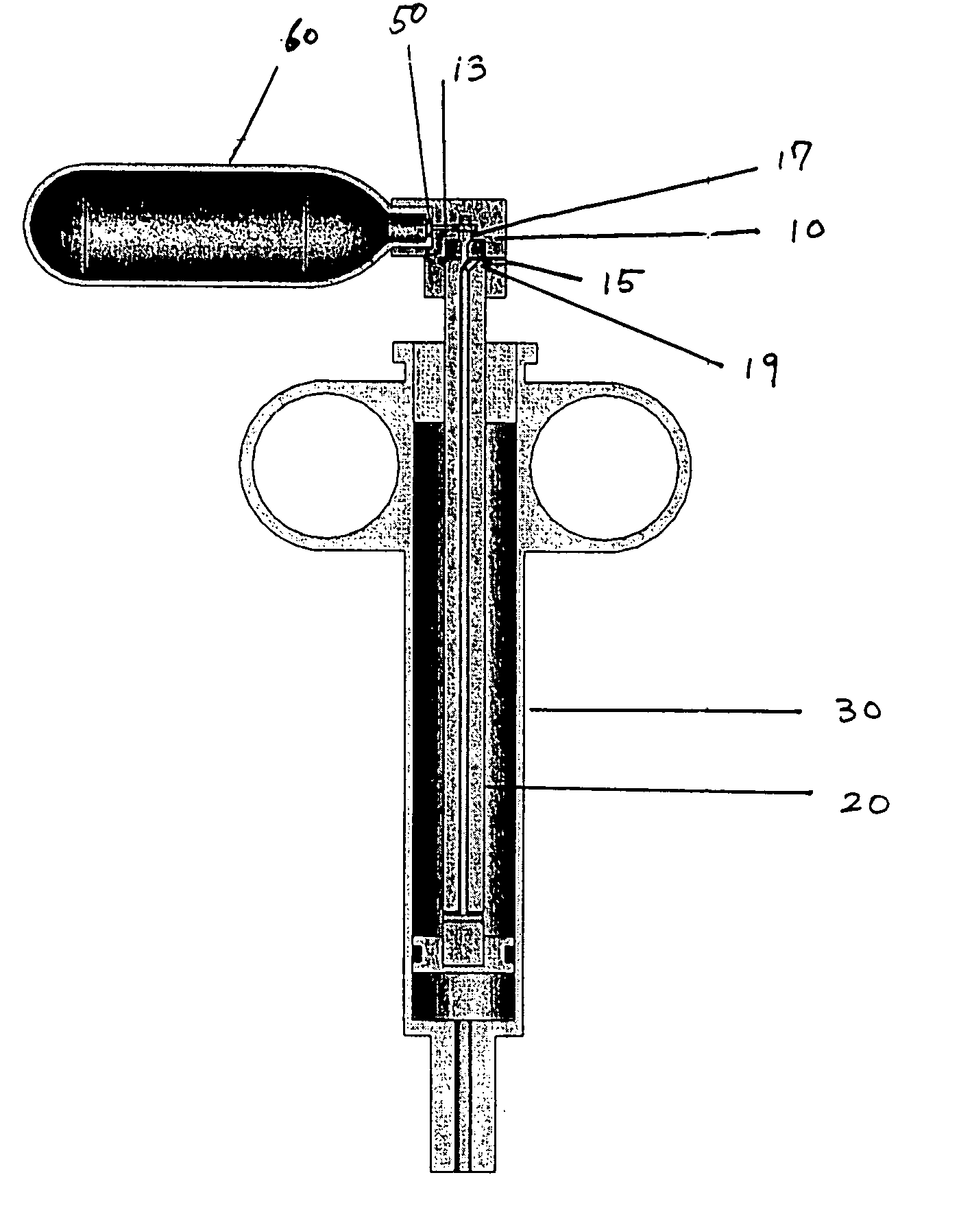
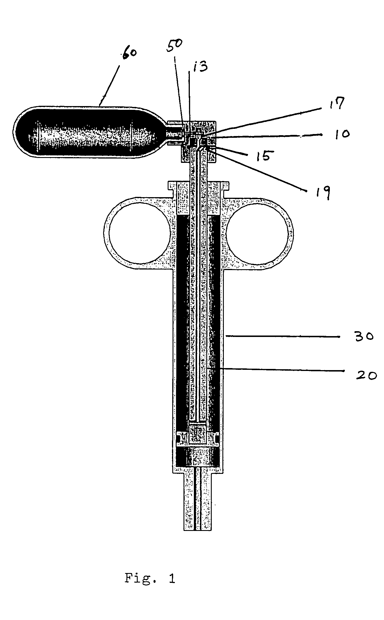
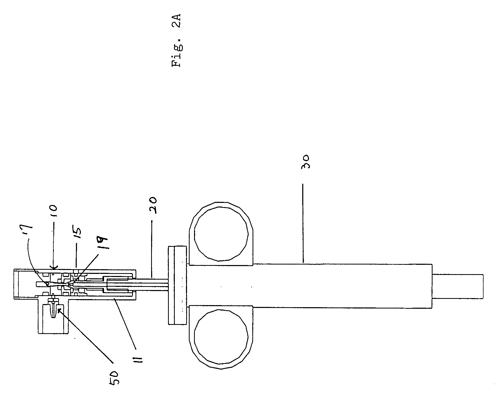
A first embodiment of the power-assisted syringe device is shown in alternative cross-sectional views by FIGS. 1, 2A and 2B respectively. FIG. 1 shows a cross-sectional perspective view of this embodiment of the power assisted syringe. FIGS. 2A and 2B are schematic illustrations of a power assisted syringe device of FIG. 1 that has been successfully tested. FIG. 2A shows a cross-sectional schematic view of an assembled device, while FIG. 2B shows a cross-sectional schematic view of an disassembled device.
As a further aid, FIGS. 3A to 3D show exploded views of these same assemblies. As seen therein, the portable and self-contained power assisted syringe comprises a manually controlled valve housing assembly 10, a plunger assembly 20, a syringe barrel assembly 30, attachment means 50 for connecting a portable source of pressurized gas to the value housing assembly 10, and a portable pressurized gas source 60 (seen as a minaturized gas cylinder). The v...
second embodiment
2. A Preferred Second Embodiment
A second embodiment of the power-assisted syringe is illustrated by FIGS. 6-9 respectively. This second embodiment is structurally and functionally similar in every respect—but two—to the first embodiment described above. The substantive differences are: (i) a plunger tube member in the plunger assembly which, for most of its linear length, is only slightly smaller in dimensions and internal spatial volume than the size and volume of the lumen in the barrel assembly; and (ii) the pressurized gas from its source is directed into and is contained solely and exclusively within the hollow channel of the plunger tube member without ever entering into the lumen of the syringe barrel as such.
FIG. 6 presents a perspective view off this second embodiment for the assembled power-assisted syringe; and FIG. 7 schematically shows the component parts of the unassembled power-assisted syringe. As seen therein, the portable and self-contained power assisted syringe...
third embodiment
3. A Preferred Third Embodiment
A third embodiment of the power-assisted syringe is illustrated by FIGS. 10-13 respectively. This third embodiment is structurally and functionally similar in every substantive respect—but two—to the first embodiment described previously herein. The substantive differences are: (i) the valve assembly is attached to the syringe on the side of the barrel assembly; and (ii) the pressurized gas from its cannister source is directed into and is contained solely and exclusively within the lumen of the syringe barrel as such—without ever entering into or travelling through the hollow channel of the plunger member in the plunger assembly.
FIG. 10 illustrates a perspective view of this third embodiment for an assembled power-assisted syringe; and FIGS. 11 and 12 respectively schematically shows the component parts of an assembled power-assisted syringe in front and side cross-sectional views. As seen therein, the power-assisted syringe device has a slidable co...
PUM
 Abstract
Description
Claims
Application Information
 - R&D
- Intellectual Property
- Life Sciences
- Materials
- Tech Scout
- Unparalleled Data Quality
- Higher Quality Content
- 60% Fewer Hallucinations
Browse by: Latest US Patents, China's latest patents, Technical Efficacy Thesaurus, Application Domain, Technology Topic, Popular Technical Reports.
© 2025 PatSnap. All rights reserved.Legal|Privacy policy|Modern Slavery Act Transparency Statement|Sitemap|About US| Contact US: help@patsnap.com


