Electrolytic capacitors with a polymeric outer layer
a polymer outer layer and capacitor technology, applied in the field of electrolytic capacitors, can solve the problems of high mechanical stress that may greatly increase the leakage current of the capacitor anode, difficult formation of a thick outer layer by in situ polymerisation, and large number of coating cycles
- Summary
- Abstract
- Description
- Claims
- Application Information
AI Technical Summary
Benefits of technology
Problems solved by technology
Method used
Image
Examples
example 1
Production of Capacitors According to the Invention
1. Production of Oxidised Electrode Bodies
[0189] Tantalum powder with a specific capacitance of 50,000 μFV / g was compacted into pellets and sintered to form a porous electrode body with dimensions of 4.2 mm*3 mm*1.6 mm. The pellets (anode pellets) were anodised in a phosphoric acid electrolyte to 30 V.
2. Chemical In Situ Coating of the Anode Pellets
[0190] A solution, comprising one part by weight 3,4-ethylenedioxythiophene (BAYTRON® M, H. C. Starck GmbH and 20 parts by weight of a 40% ethanolic solution of iron(III)-p-toluenesulphonate (BAYTRON® C-E, H. C. Starck GmbH) was produced.
[0191] The solution was used to impregnate 9 anode pellets. The anode pellets were steeped in this solution and then dried for 30 min at ambient temperature (20° C.). They were then heat treated for 15 min at 50° C. and 15 min at 150° C. in a drying oven. The pellets were then washed for 30 min in water. The anode pellets were reformed for 30 min ...
example 2
Production of Capacitors According to the Invention
[0197] Tantalum powder with a specific capacitance of 50,000 μFV / g was compacted into pellets and sintered to form a porous electrode body with dimensions of 4.2 mm*3 mm*0.8 mm. The pellets (anode pellets) were anodised in a phosphoric acid electrolyte to 30 V.
[0198] The chemical in situ coating and application of the polymeric outer layer were carried out according to Example 1 (step 2 and 3).
[0199] After application of the polymeric outer layer, the anode pellets were observed under a light microscope: the entire external surface was covered with a dense polymer film. The edges exhibited a continuous polymer film coating.
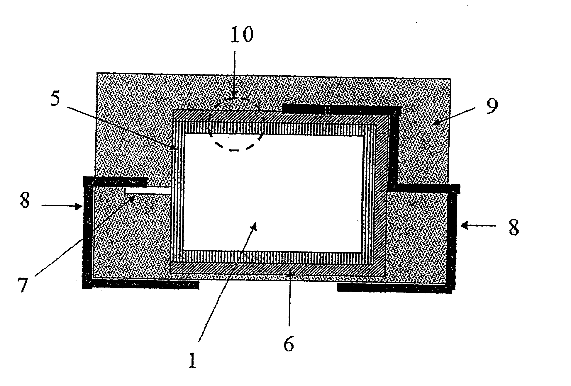
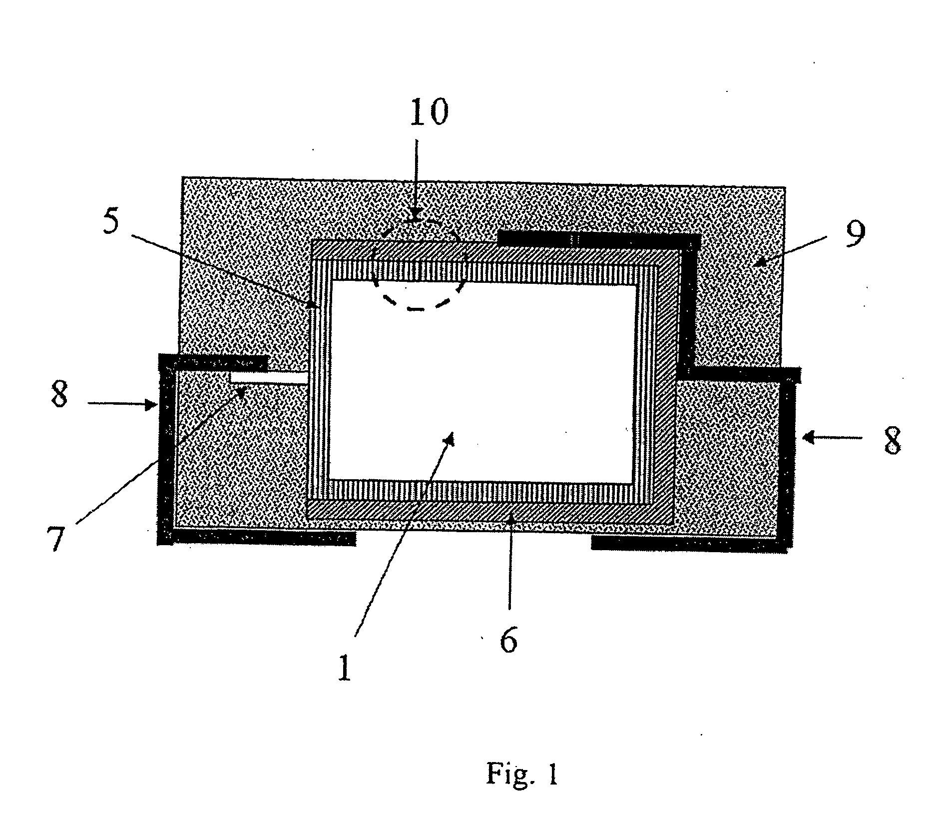
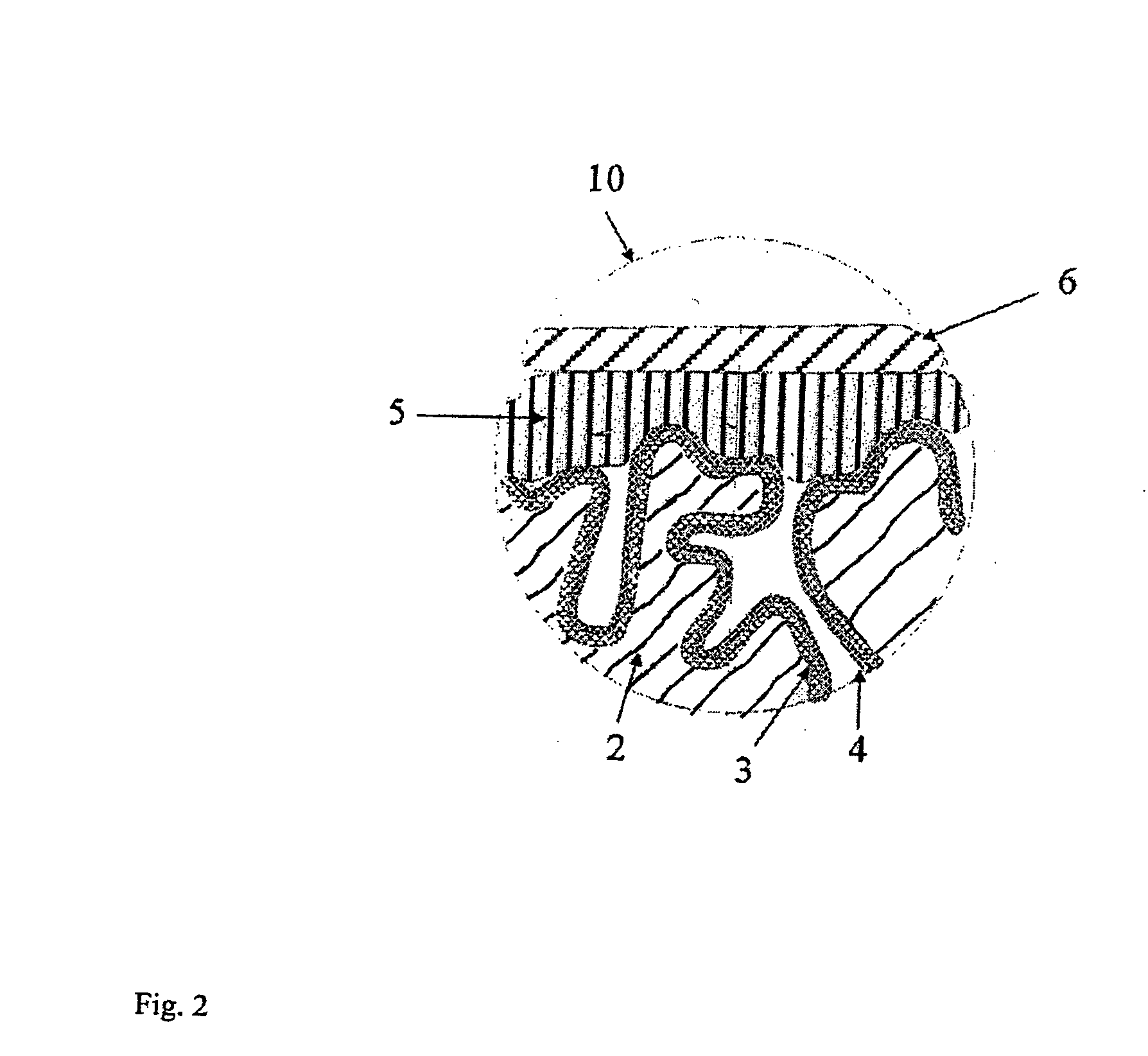
[0200]FIG. 3 shows a light microscopic photograph of a fractured surface of the capacitor according to the invention. An approximately 5 to 10 μm thick polymer outer layer that also very effectively surrounds the edge of the capacitor pellet may clearly be seen.
[0201] Two of the anode pellets were coated wit...
example 3
Resistance of Capacitors According to the Invention to Mechanical Stresses
[0213] The capacitors according to the invention from Example 1 were contacted on the silver layer by means of a metal spring bolt (spring force 3 N, round bearing surface with diameter of 1.5 mm, bearing pressure approximately 170 N / cm2 or 17 bar) for measuring leakage current.
[0214] The leakage current at 10 V increased with this high mechanical stress from, on average, 5 μA to 144 μA.
[0215] The capacitors not according to the invention from Example 4A with an outer layer polymerised in situ were subjected to the same stress test. A 10 V voltage could not be applied to the 6 capacitors with a leakage current of 1 μA from Example 4A without electrical short-circuits being produced. Even at 0.5 V the capacitors exhibited an average leakage current of almost 2,000 μA.
[0216] This example shows that the capacitors according to the invention have high stability to mechanical stresses.
PUM
| Property | Measurement | Unit |
|---|---|---|
| thick | aaaaa | aaaaa |
| temperatures | aaaaa | aaaaa |
| thickness | aaaaa | aaaaa |
Abstract
Description
Claims
Application Information
 - R&D
- Intellectual Property
- Life Sciences
- Materials
- Tech Scout
- Unparalleled Data Quality
- Higher Quality Content
- 60% Fewer Hallucinations
Browse by: Latest US Patents, China's latest patents, Technical Efficacy Thesaurus, Application Domain, Technology Topic, Popular Technical Reports.
© 2025 PatSnap. All rights reserved.Legal|Privacy policy|Modern Slavery Act Transparency Statement|Sitemap|About US| Contact US: help@patsnap.com


