Nitrogen recovery system and method using heated air as stripping gas

Inactive Publication Date: 2005-06-30
ENVIRONMENTAL ENERGY & ENG
View PDF46 Cites 61 Cited by
  • Summary
  • Abstract
  • Description
  • Claims
  • Application Information

AI Technical Summary

Benefits of technology

[0008] Using heated air as the stripping gas will increase the removal of carbon dioxide and ammonia. Using heated air will also increase the temperature of the bi

Problems solved by technology

The lower temperature will also negatively affect the efficien

Method used


Image

  • Nitrogen recovery system and method using heated air as stripping gas
  • Nitrogen recovery system and method using heated air as stripping gas

Examples


Embodiment Construction

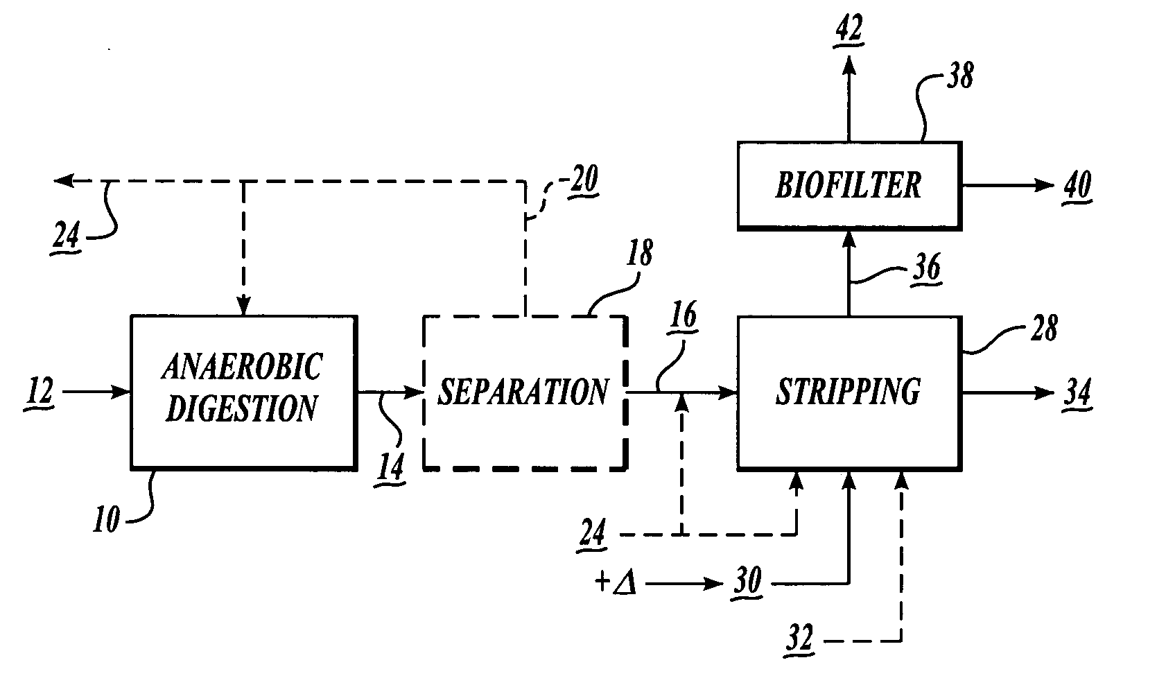
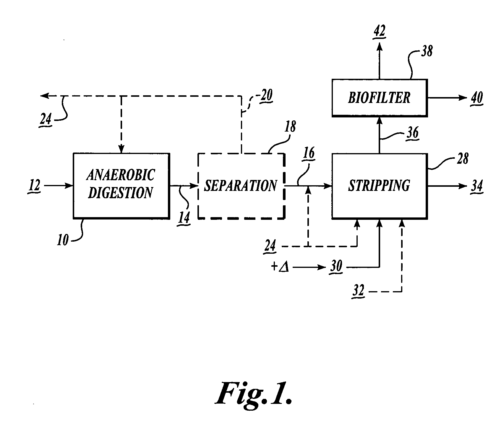
[0011]FIG. 1 schematically illustrates one embodiment of a method according to the present invention. Anaerobically digesting liquid waste 10, such as flush water containing cow manure from dairy farms, is followed by gas stripping or desorption 28 of dissolved carbon dioxide and ammonia from the digested liquid. The stripped gases are treated in a bacteria-activated “biofilter”38, that converts ammonia into nitrate compounds and other nitrogenous compounds that can then be used as fertilizer. The method according to the invention combines the processes of anaerobic digestion, desorption, and nitrification to advantageously recover nitrogen, which would otherwise be discharged into the atmosphere.

[0012] The system to carry out the method according to the present invention, includes an anaerobic digester 10, a gas desorption or stripping unit 28, a nitrification absorption unit or biofilter 38, and optionally a solids separator 18. It is to be appreciated that the figure represents ...


PUM

PropertyMeasurementUnit
Temperatureaaaaaaaaaa

Abstract

A process for the recovery of nitrogen from anaerobically digested liquid waste and for the collection of the nitrogen as nitrate compounds that can be used to produce fertilizer and compost, includes stripping ammonia from anaerobically digested liquid waste, and converting the ammonia into nitrates via nitrification. The stripping gas is heated above ambient atmospheric temperature to improve nitrogen recovery. The heat can be reclaimed by burning gases generated during the anaerobic digestion process.

Description

CROSS-REFERENCES TO RELATED APPLICATIONS [0001] This application is a continuation-in-part of application Ser. No. 10 / 625,198, filed Jul. 22, 2003, which claims the benefit of Provisional Application No. 60 / 398,296, filed Jul. 22, 2002, both incorporated herein by reference in their entirety.FIELD OF THE INVENTION [0002] The field of the invention is related to the removal and recovery of nitrogen from anaerobically digested liquid waste and the collection of the nitrogen as nitrates and organic nitrogen compounds that can be used to produce fertilizer and compost. BACKGROUND OF THE INVENTION [0003] In U.S. application Ser. No. 10 / 625,198, fully incorporated herein by reference in its entirety, a method is described that is related to the recovery of nitrogen from ammonia that is produced from anaerobic digestion of waste. In the prior process, atmospheric air at ambient temperature is used as the stripping gas. However, if ambient air is used, especially during winter, the temperat...

Claims


Application Information

Patent Timeline
IPC IPC(8): C02F1/02C02F1/20C02F1/24C02F1/66C02F3/00C05F3/00C05F17/00
CPCC02F1/001Y02E50/343C02F1/20C02F1/24C02F1/66C02F3/06C02F3/28C02F3/30C02F3/302C02F2101/16C02F2103/20C05F3/00C05F17/0018C05F17/0027C05F17/0054Y10S210/903C02F1/02C05F17/15C05F17/40C05F17/50Y02A40/20Y02E50/30Y02P20/145Y02W10/10Y02W30/40
Inventor BURKE, DENNIS A.
Owner ENVIRONMENTAL ENERGY & ENG
Why Eureka
Try Eureka