Perpendicular magnetic recording medium and a method for manufacturing the same

a technology of magnetic recording medium and perpendicular magnetic, which is applied in the field of perpendicular magnetic recording medium, can solve the problems of reducing the magnetic interaction between the magnetic grains, affecting the durability of this type of device, and substantial degradation of the durability of the medium, so as to enhance the corrosion resistance, improve the electromagnetic conversion characteristic, and improve the recording density

Active Publication Date: 2005-07-14
FUJI ELECTRIC CO LTD
View PDF7 Cites 66 Cited by
  • Summary
  • Abstract
  • Description
  • Claims
  • Application Information

AI Technical Summary

Benefits of technology

[0029] Because a heating step is inserted after the step of forming the first magnetic layer and before the step of forming the second magnetic layer, the second magnetic layer grows while retaining the same grain size and same grain boundary width as those of the first magnetic layer. Segregation of the nonmagnetic element in the nonmagnetic grain boundary region in the second magnetic layer is drasticall

Problems solved by technology

Reduction of magnetic interaction between magnetic grains also is a problem in attaining high recording density in perpendicular magnetic recording media.
Durability of this type of device is strongly affected by friction and wear characteristics between the head and the medium.
It is known that precipitation of cobalt atoms contained in the magnetic layer of the medium to the medium surfa

Method used


Image

  • Perpendicular magnetic recording medium and a method for manufacturing the same
  • Perpendicular magnetic recording medium and a method for manufacturing the same
  • Perpendicular magnetic recording medium and a method for manufacturing the same

Examples


example 1

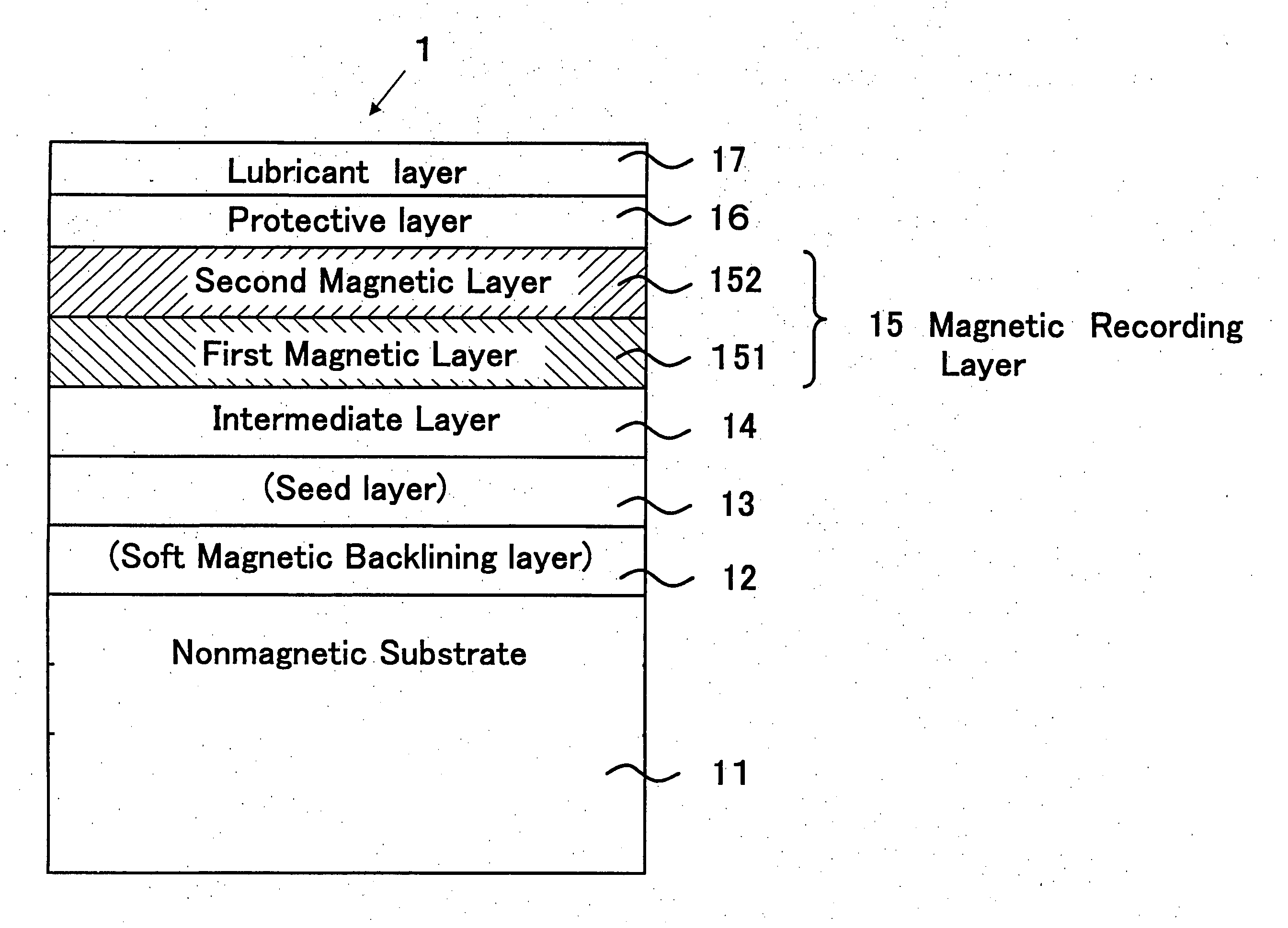
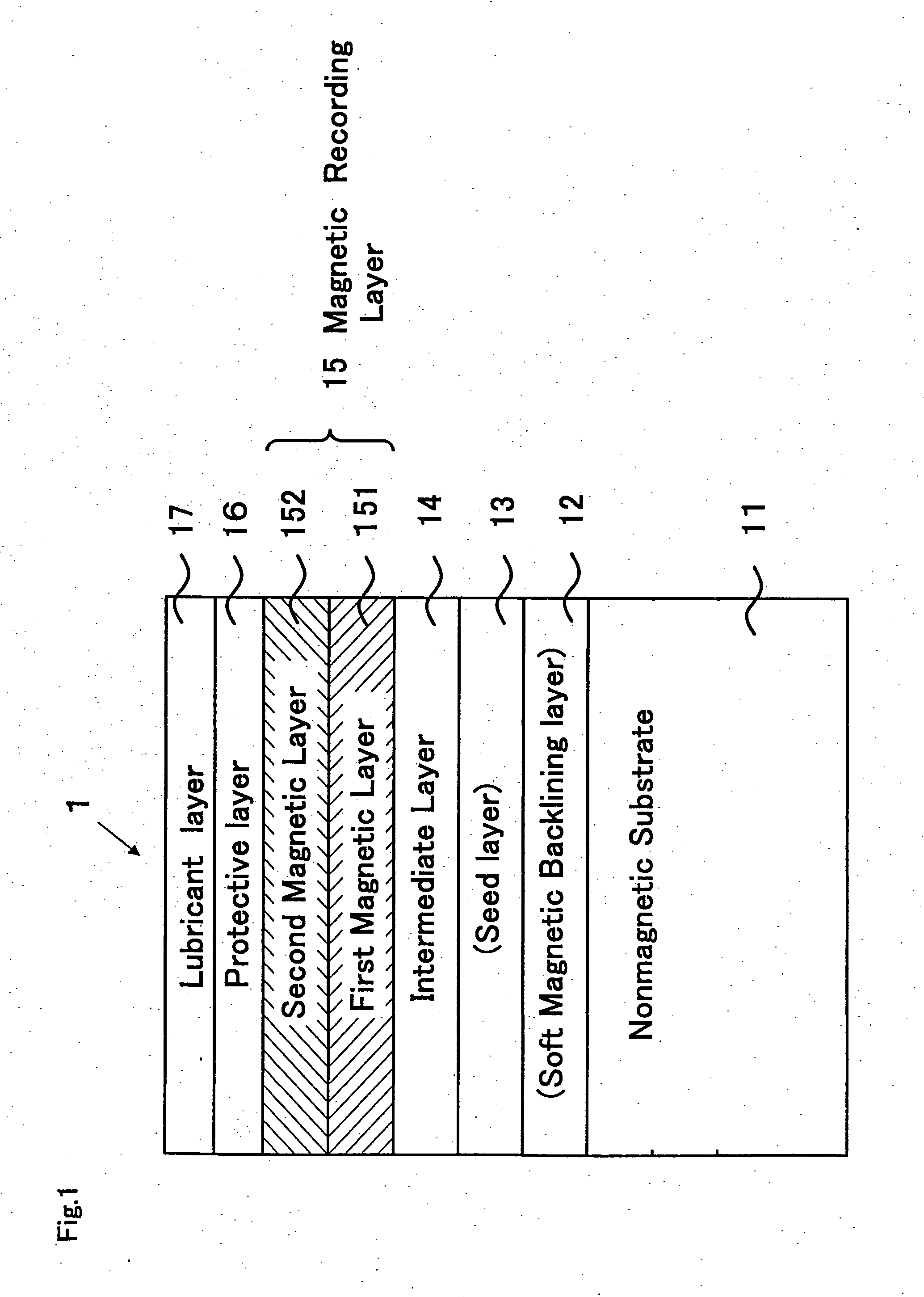
[0059] Perpendicular magnetic recording medium 1 as shown in FIG. 1 was produced in Example 1 except that seed layer 13 in FIG. 1 was not provided. Nonmagnetic substrate 11 was a chemically reinforced glass substrate with a smooth surface (for example, N-5 glass substrate made by HOYA Corporation). After cleaning, the substrate was put into a sputtering apparatus. Sequentially deposited layers were amorphous soft magnetic backlining layer 12 of CoZrNb 200 nm thick, intermediate layer 14 of ruthenium with a thickness of 30 nm, first magnetic layer 151 having a thickness of 20 nm deposited by an RF sputtering method using a target of CoCrPt—SiO2, and second magnetic layer 152 having a thickness of 10 nm deposited using a target of CoCrPtB. The first magnetic layer and the second magnetic layer were formed in various conditions of sputtering gas pressures in Example 1. After depositing protective layer 16 of carbon 5 nm thick, the substrate was taken out from the vacuum chamber. Finall...

example 2

[0066] Heat treatment after deposition process of the magnetic recording layer is conducted in Example 2. Magnetic recording media of Example 2 were produced in the same manner as in Example 1 except that substrate heating before deposition (pre-heating), and heating after deposition of the second magnetic layer (post heating) and subsequent fast cooling were conducted in one apparatus. Gas pressures in the deposition process were 50 mTorr for the first magnetic layer and 5 mTorr for the second magnetic layer, and not varied throughout the media of Example 2.

[0067] Preheating temperature was 200° C. and post heating temperature was 200° C. Fast cooling step subsequent to the post heating was adjusted so that the substrate temperature cooled down to 100° C. in 10 sec. Coercivity Hc and SNR were measured on media with or without each of the three heat treatment steps. Table 3 summarizes the results.

TABLE 3pre-postfastHcSNR atheatingheatingcooling(Oe)350 kFCI (dB)nonenonenone3,50017...

example 3

[0069] Magnetic recording media were produced in the same manner as in Example 1 except that intermediate layer 14 with a thickness of 30 nm was formed of various materials. Gas pressures in deposition processes were 50 mTorr for the first magnetic layer and 5 mTorr for the second magnetic layer, and not changed throughout the media of Example 3. Table 4 summarizes half width Δθ50 of a rocking curve of hcp (002) diffraction line of the magnetic recording layer measured by X-ray diffraction. Table 4 includes the cases of intermediate layers formed of tantalum and chromium both having a bcc structure for comparison.

TABLE 4intermediate layerintermediate layerΔθ50materialcrystal structure(deg)Ruhcp5.0Re5.6Os6.5Ti8.1Ru-20% W4.9  Ti-10% Cr7.5Tabcc25.0Cr20.4

[0070] Table 4 indicates improvement of Δθ50 by the intermediate layers composed of materials having an hcp structure as compared with the intermediate layer of tantalum and chromium having a bcc structure, demonstrating effective cry...


PUM

PropertyMeasurementUnit
Pressureaaaaaaaaaa
Pressureaaaaaaaaaa
Grain sizeaaaaaaaaaa

Abstract

A perpendicular magnetic recording medium has a magnetic recording layer and laminated magnetic layers composed of different materials. In a first magnetic layer of the magnetic recording layer, ferromagnetic grains are surrounded by a nonmagnetic grain boundary region composed principally of oxide and/or nitride. In a second magnetic layer of the magnetic recording layer, ferromagnetic grains are surrounded by a nonmagnetic grain boundary region composed principally of chromium. The recording medium has an intermediate layer composed of a material having hcp or fcc structure. Advantageously, a heating process is conducted after forming the first magnetic layer and before forming the second magnetic layer. The medium achieves improvement in electromagnetic conversion characteristics and simultaneously improvement in corrosion resistance to provide a perpendicular magnetic recording medium with high recording density and simultaneously high reliability.

Description

CROSS REFERENCE TO RELATED APPLICATIONS [0001] This application claims priority from Japanese application Serial No. 2004-003365, filed on Jan. 8, 2004, and the contents of this document are incorporated herein by reference in their entirety. BACKGROUND OF THE INVENTION [0002] A. Field of the Invention [0003] The present invention relates to a perpendicular magnetic recording medium mounted on various magnetic recording apparatuses, and to a manufacturing method therefor. [0004] B. Description of the Related Art [0005] A perpendicular magnetic recording system in which recording magnetization is perpendicular to a medium surface is being explored as a technology for achieving higher density in magnetic recording than that achieved by conventional longitudinal magnetic recording systems. [0006] A perpendicular magnetic recording medium is mainly composed of a magnetic recording layer of hard magnetic material, an intermediate layer for aligning the magnetic recording layer to a speci...

Claims


Application Information

Patent Timeline
IPC IPC(8): G11B5/64G11B5/65G11B5/66G11B5/667G11B5/73G11B5/738G11B5/84G11B5/851
CPCG11B5/65G11B5/656G11B5/66G11B5/851G11B5/732G11B5/7325G11B5/84G11B5/667G11B5/7379G11B5/7368G11B5/7377G11B5/7369G11B5/672
Inventor WATANABE, SADAYUKISAKAI, YASUSHIUWAZUMI, HIROYUKI
Owner FUJI ELECTRIC CO LTD
Why Eureka
Try Eureka