
Optical system and method for inspecting fluorescently labeled biological specimens

Inactive Publication Date: 2005-08-18
D N R - IMAGING SYST
View PDF1 Cites 25 Cited by
  • Summary
  • Abstract
  • Description
  • Claims
  • Application Information

AI Technical Summary

Benefits of technology

[0010] The use of fluorescent probes routinely for diagnostic purposes creates new standards and demands for a fluorescent detection system. Such a system must provide a complete and full solution for a fluorescent-based diagnosis. The system must be characterized by a high throughput capability, high levels of automation, a simple graphic user interface (GUI) that enables minimal user operating mistakes and thereby allows for layman operation of the system, a high level of reliability and accuracy, and last but not least, it must be economically beneficial.
[0012] The technique of the present invention thus provides a unique platform that complies with the new demands arising from turning the latest research techniques in fluorescence into tomorrow's diagnostic tools. The system and method of the present invention makes up a Fluorescent Working Station (F-WOS) constructed and operated to provide optimal conditions for acquiring high-end fluorescent images (i.e., the combination of low light sensing, small size and high magnification, together with the enhanced image processing and control) from biological samples for research and diagnostic tasks, and to provide optimal conditions for the sample, fluorescent signals, operator, and all other personal working in the lab. By designing a complete system especially for fluorescent diagnostics, the high performance, high throughput, and low price system is obtained. It should be noted that fluorescent signals, for diagnostic tasks, are characterized by a low light (about 0.001 lux), capability of detecting small size fluorescent labels (0.1-0.4 microns), fast fluorescent intensity decay with time (bleaching), and environmental sensitivity. This means that in fluorescent imaging, working on the “edge” of technology is required, and it is thus crucial to address the fluorescent signal quality issues, as well as the imaging quality issues, for obtaining the best results.
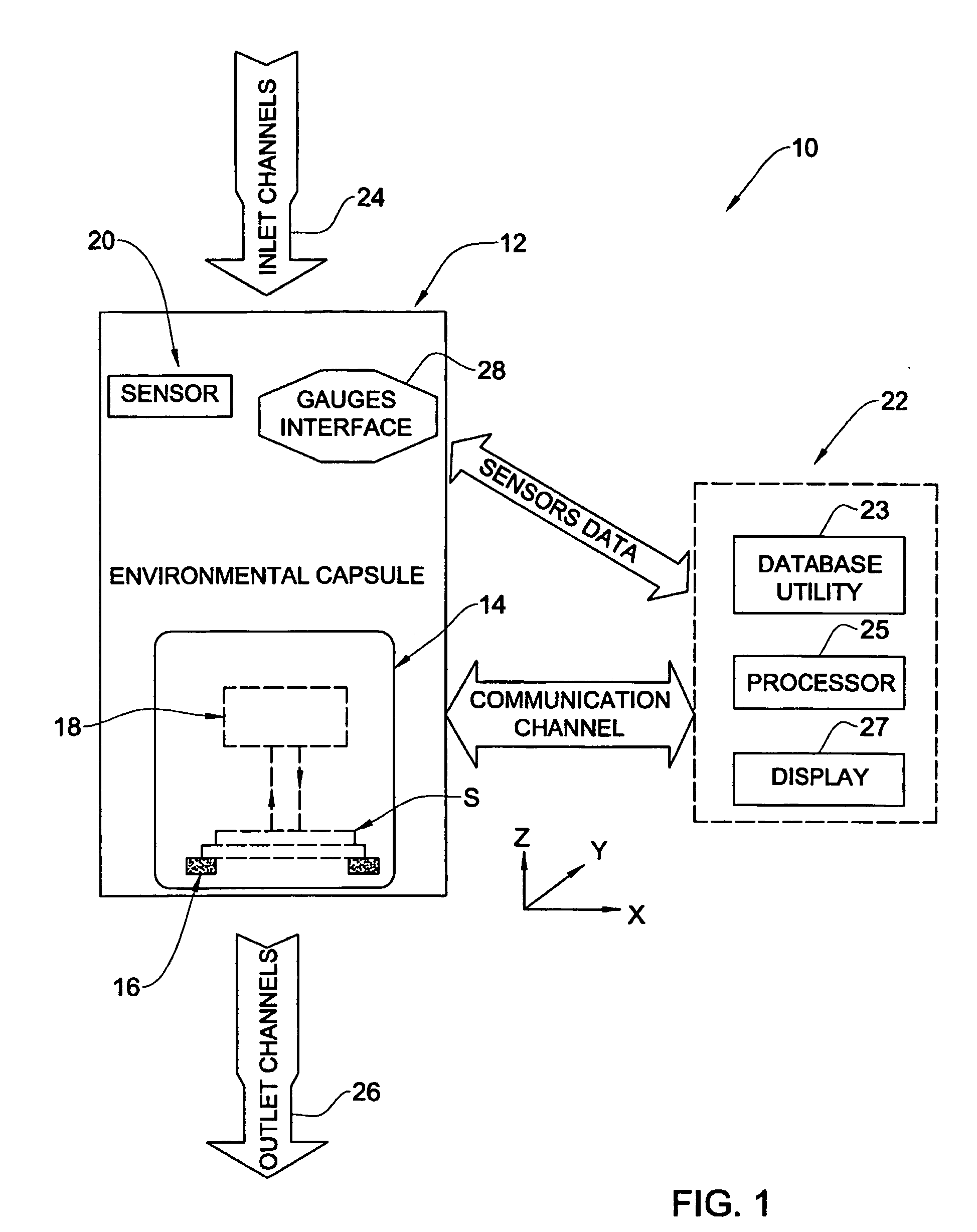
[0013] The F-WOS of the present invention is the first fluorescent-based system that makes a significant effort in improving the quality of the fluorescent signals, and not just improving the quality of the acquired images. The F-WOS enables to easily load a fluorescent slide into the capsule, automatic scanning of the slide in the X,Y,Z planes at the appropriate resolution and speed, searching for the designated regions of interest on the fly, and optimal acquisition of the required images for research and diagnosis needs.
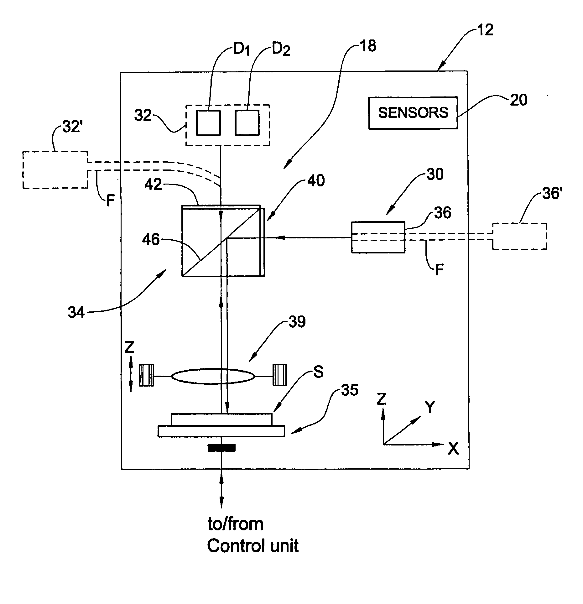
[0015] Preferably, the capsule comprises one or more sensors for sensing the environment condition(s) inside the capsule to be controlled, and inlet and outlet means enabling to desirably affect the corresponding condition(s) inside the capsule. The capsule thus presents a “controlled environmental capsule” (CEC). The sensors suitable to be used in the capsule include at least one of the following: a temperature sensor, an ambient light sensor, an electromagnetic radiation sensor, oxygen or other gases' sensor, and a humidity sensor. The CEC is designed to protect the biological media and the fluorescent probes therein from environmental hazards, and to provide them with optimal conditions during the imaging. For example, the capsule protects the sample from unwanted light in the room, high temperature, and the presence of oxygen, causing the sample to fade quickly (the Bleaching phenomena). Providing these optimal conditions for the fluorescent sample improves the quality of the fluorescent signals. The CEC also provides protection for the operating personal from hazardous conditions of the system such as the use of UV light. Furthermore, the encapsulation of the sample with the optical device enables installation of the working station in any room or laboratory, without the necessity to darken the room when working with the fluorescent signals, thus stopping all other activities in the laboratory at that time.
[0018] The device further includes a scanning system, which enables scanning the sample at different resolution and speeds at the X, Y and Z directions (3D scanning). The scanning system supports the ROI search and identification, preferably utilizing also auto-focusing abilities, and provides the F-WOS with the ability to automatically detect a large amount of fluorescent signals in a short period of time.

Problems solved by technology

However, the detection of fluorescent probes in a biological sample by means of the conventional fluorescent microscope suffers from several drawbacks associated with the following.
The operator has to look through a binocular eyepiece during the entire process, which is a cumbersome and tiring process.
Thus, an operator cannot work on the microscope for more than a few hours continuously, and not more than 8-10 hours daily.
This of course limits the number of tests a lab can perform, thus limiting the lab's throughput significantly.
Furthermore, the laboratory, where this analysis is done, has to be in blackout conditions.
This is associated with one of the major problems of using fluorescent labeling for routine diagnostic assays, consisting of keeping the fluorescent labeling “alive” long enough to finish the entire procedure, which typically includes scanning the sample on a slide, looking for region of interests (ROIs) in the sample (for example, a nucleus of the cell or a chromosome), focusing on the ROIs, taking an image thereof, refocusing on sub areas within the ROI (for example labeled genes), and taking images of the these sub areas as well.
Working for so long on the sample raises the problem of bleaching.
Bleaching of a sample causes the fluorescent probes to fade, thus making the reading of the sample impossible.
Operation with the conventional fluorescent microscope thus requires operation in the dark, and implies that other activities requiring light cannot be carried out at the same time and place, when fluorescent analysis is in process.
Furthermore, the necessity to work in a dark environment, affects the performance of the microscope operator.
Working in the dark, is no doubt, a cumbersome task.
Other environmental hazards of the conventional techniques, such as heat, humidity, radiation, electromagnetic waves, also have undesired influence on some biological samples.
With the conventional microscope and conventional technique, operating personnel are exposed to safety hazards due to UV light typically used to excite the fluorescent sample, but is harmful to people.
However, using the “off-the-shelf” components that were not designed specifically for fluorescent diagnostic tasks (to comply with the demands of the fluorescent-based diagnostic world) obviously decreases performance and increases costs of the optical system.

Method used


Image

  • Optical system and method for inspecting fluorescently labeled biological specimens
  • Optical system and method for inspecting fluorescently labeled biological specimens
  • Optical system and method for inspecting fluorescently labeled biological specimens

Examples


Embodiment Construction

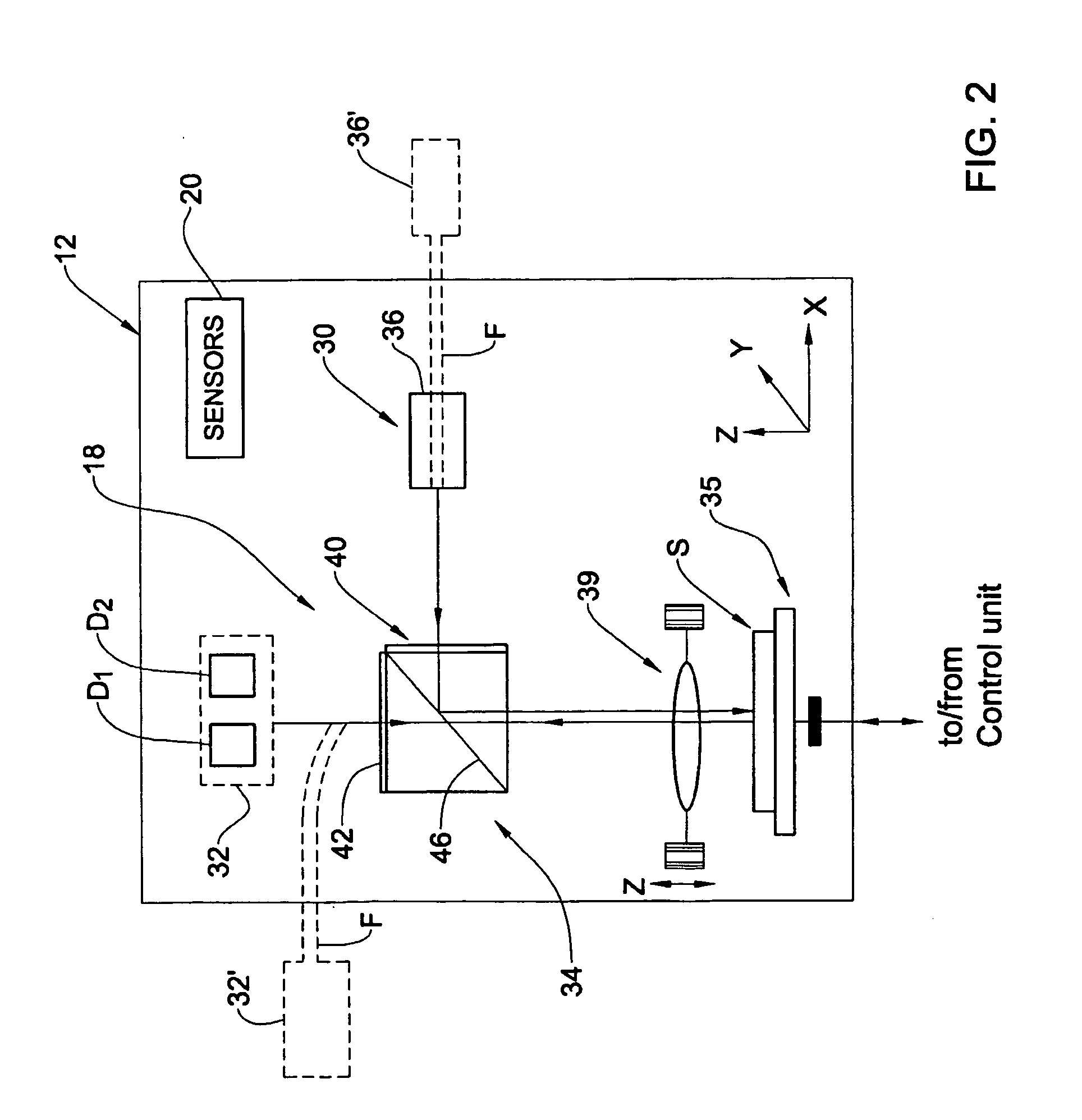
[0034] Referring to FIG. 1, there is schematically illustrated an optical system 10 according to the invention for imaging fluorescently labeled samples. The system 10 comprises a control environment capsule (CEC) 12 that is formed with a door 14 for receiving a sample-on-slide S and includes a stage 16 for supporting the sample S during the system operation, and an optical device 18. The sample is a biological specimen that should be prevented from being illuminated all the time except for that needed for imaging the sample. To this end, the sample-on-slide may be stored in a “pre-loading” cassette designed for carrying a single slide or multiple slides in darkness. The slide can be manually loaded onto the stage 16, or automatically by means of a robot. This can be implemented by an automatic movement of the stage 16 into a loading position when the door 14 is opened. If the slide in cassette is used, the cassette can be formed with a shiftable cover that is automatically shifted ...


PUM


Abstract

A system for imaging a fluorescently labeled sample is presented, The system comprises a capsule, which is a closable structure made of a material isolating the inside of the capsule from its surrounding environment, and which has a support stage for receiving the sample and carrying it thereinside during the imaging; and an optical device at least partly accommodated inside the capsule and operable to illuminate the sample with incident radiation to excite a fluorescent response of the sample, detect the fluorescent response, and generate data indicative thereof.

Description

FIELD OF THE INVENTION [0001] This invention is generally in the field of optical measurement / inspection techniques and relates to an optical system and method for inspecting fluorescently labeled biological specimens. BACKGROUND OF THE INVENTION [0002] One of the new emerging techniques used today in the research of molecular biology and genetics is fluorescent labeling of a biological specimen. According to this technique, fluorescent probes are used to mark the specific locations in a biological specimen aimed at detecting different genes, chromosomes, DNA strands, proteins, and bacteria. [0003] In recent years, the fluorescent labeling based techniques have started to push their way into the diagnostic world, and it is anticipated that in the near future diagnostic assays based on fluorescent labeling will be used more and more routinely. [0004] According to conventional techniques, the detection of fluorescent probes is done in research laboratories by using an “off the shelf” ...

Claims


Application Information

Patent Timeline
IPC IPC(8): G01N21/35G01N21/64
CPCG01N21/3504G01N21/6458G01N21/6428
Inventor PALTI-WASSERMAN, DAPHNAKOBER, YARONKELLY, EREZ
Owner D N R - IMAGING SYST
Learn More