
Apparatus and method for small-volume fluid manipulation and transportation

a fluid manipulation and fluid transportation technology, applied in the field of miniature instruments, can solve the problems of difficult to arrange all the capillary tubes tightly to occupy a very small space, difficult to form zero-dead volume connectors using conventional capillary tubes, and difficult to connect fia conduits and pump capillaries via ion exchangeable membrane tubes. achieve the effect of simple fluid manipulation and transportation, and facilitate high throughput assays

Inactive Publication Date: 2005-09-01
LIU SHAORONG +1
View PDF4 Cites 32 Cited by
  • Summary
  • Abstract
  • Description
  • Claims
  • Application Information

AI Technical Summary

Benefits of technology

[0016] The present invention overcomes shortcomings of prior art microfluidic pumping systems and enables new applications in the field of microfluidics. In one aspect of the present invention, a microfabricated EOF pump on a microchip is disclosed which utilizes a microfabricated channel or channels to generate EOF as its pumping means. The present invention also utilizes a bubble-free electric connection joint on the chip to separate the microfabricated pump channel(s) from the chemical assay conduit(s) while maintaining hydraulic connectivity between these two parts. The present invention also permits many pump channels to be constructed for a single pump to generate sufficient flow rate with sufficient pumping power and multiple pumps to be constructed on a single chip to facilitate high throughput assays and complicated fluid manipulations and transportations. It also permits zero dead-volume connections between microfluidic channels.
[0018] Another object of the present invention is to provide a method and apparatus that utilizes a bubble-free electric connection joint to separate the pump channels from the rest of the microfluidic conduits such that the connection joint is electrically grounded and allows the microfabricated pump to manipulate fluids in microfluidic devices but prevents the electric field on the pump from interfering with the rest of the microfluidic conduits on the chip. It also permits application of an electric potential to the microfluidic conduits when needed;
[0019] Another object of the present invention is to provide a method and apparatus that utilizes an isolation channel to separate the pump channels from the rest of the microfluidic network such that the isolation channel maintains hydraulic connectivity between the pump channels and the rest of the microfluidic network but prevents the fluids in the microfluidic network from contaminating the pump channels and pump solution;
[0020] Another object of the present invention is to provide a bubble-free electrode that permits application of an external voltage / current source to a microfluidic channel but prevent bubbles from forming in the microfluidic channel;

Problems solved by technology

To increase the fluid flow rate, multiple capillaries are used, but in practice, connecting the FIA conduits and pump capillaries via the ion exchangeable membrane tube becomes tedious and commercially impracticable.
Additionally, when many capillary tubes are desired to generate sufficient flow rate and pressure, it is very difficult to arrange all the capillary tubes tightly to occupy a very small space.
Furthermore, when fluids in the FIA system need to be merged and / or split with zero-dead volume, it is impossible to form zero-dead volume connectors using conventional capillary tubes.
Finally, it is very difficult to construct a compact system with multiple pumps using the configuration disclosed in U.S. Pat. No. 5,573,651, especially when configuring parallel FIA systems.
In Analytical Chemistry, 1994, 66, 1792-1798, two EOF pumps were used in a two-line FIA system to facilitate reliable measurements of chloride, but the pump electrolyte solution containers and pump capillaries made the system bulky compared to the volumes of solutions handled.
This pump however would be insufficient to propel fluids on chips because any backpressure from the system will make the fluid flow to the cathode channel.
In addition to the aforementioned difficulties, previous microchip EOF pump implementations have proven unsatisfactory because of variations introduced by electric fields, which are generally applied across the entire system to balance fluids moving in the conduit network.
It is extremely challenging, if not impossible, to balance the fluid flow reliably when the ionic strength of a sample changes, adsorption of substances occurs on the channel surfaces, the solution pH varies, or the system temperature shifts.
This roller based method is not practical for microfabricated systems, especially when complicated fluid movements are required.
Using this method however, it is very difficult to control the fluid flow in complex devices.

Method used


Image

  • Apparatus and method for small-volume fluid manipulation and transportation
  • Apparatus and method for small-volume fluid manipulation and transportation
  • Apparatus and method for small-volume fluid manipulation and transportation

Examples


example 1

Microfabrication of Glass Chips

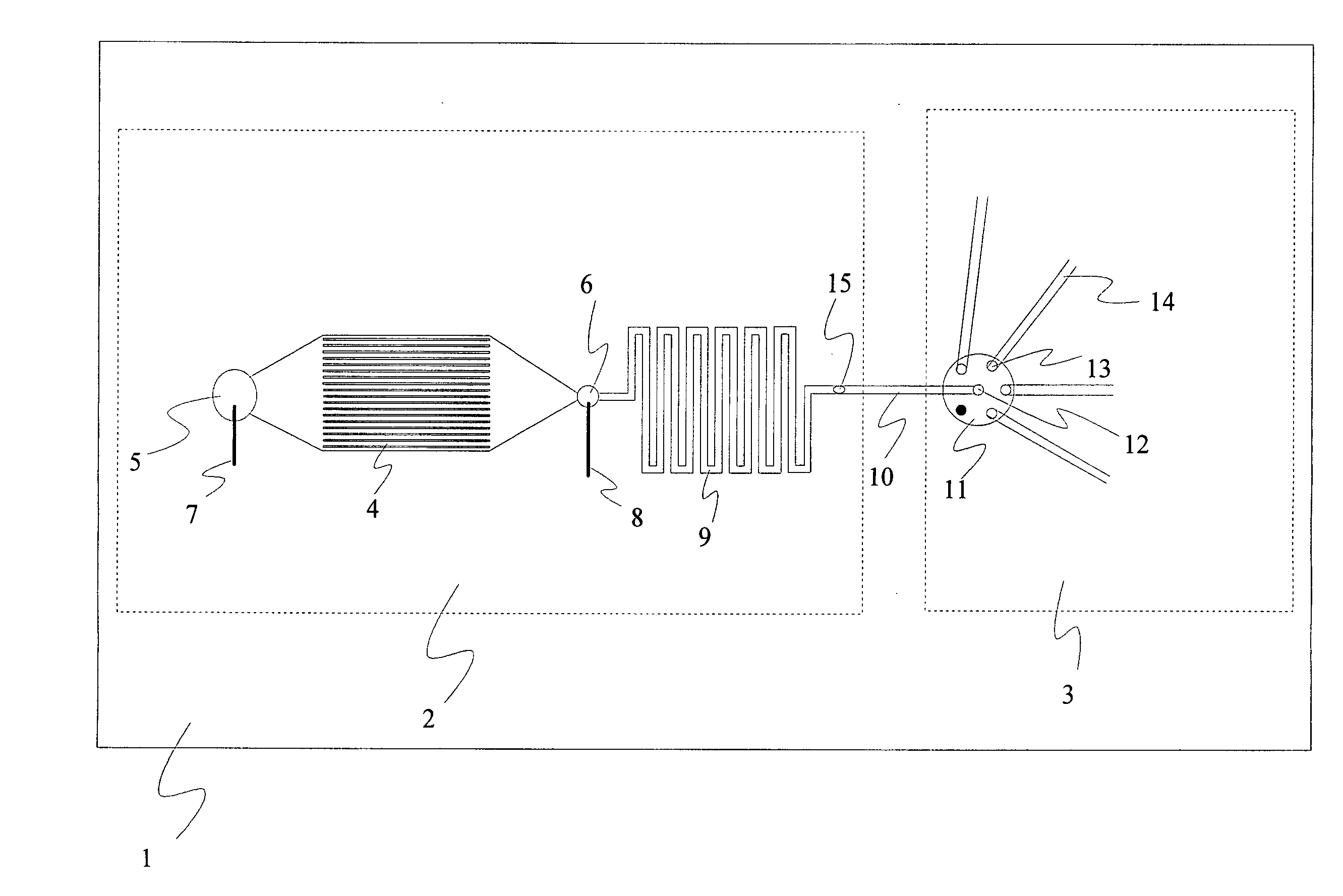
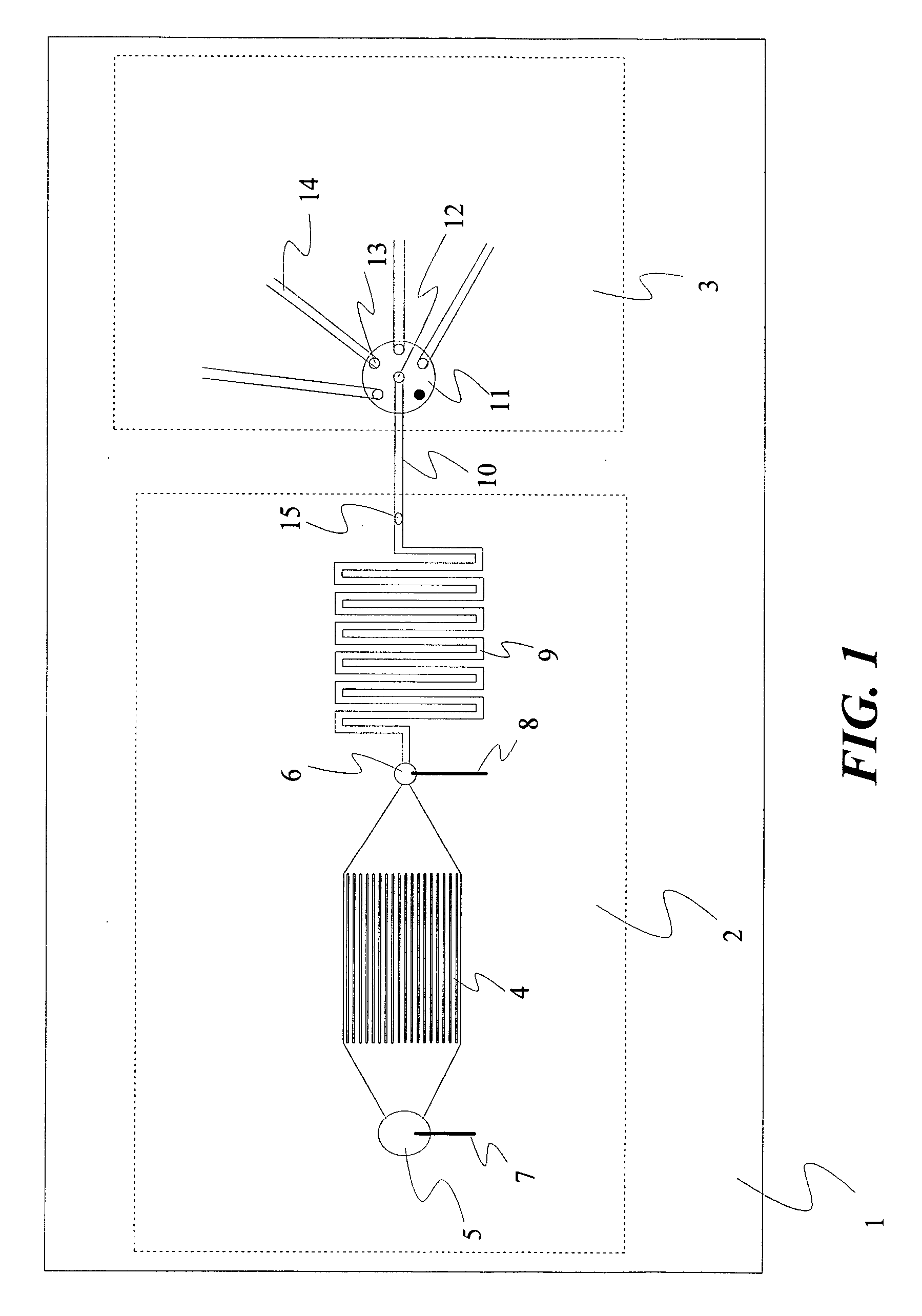
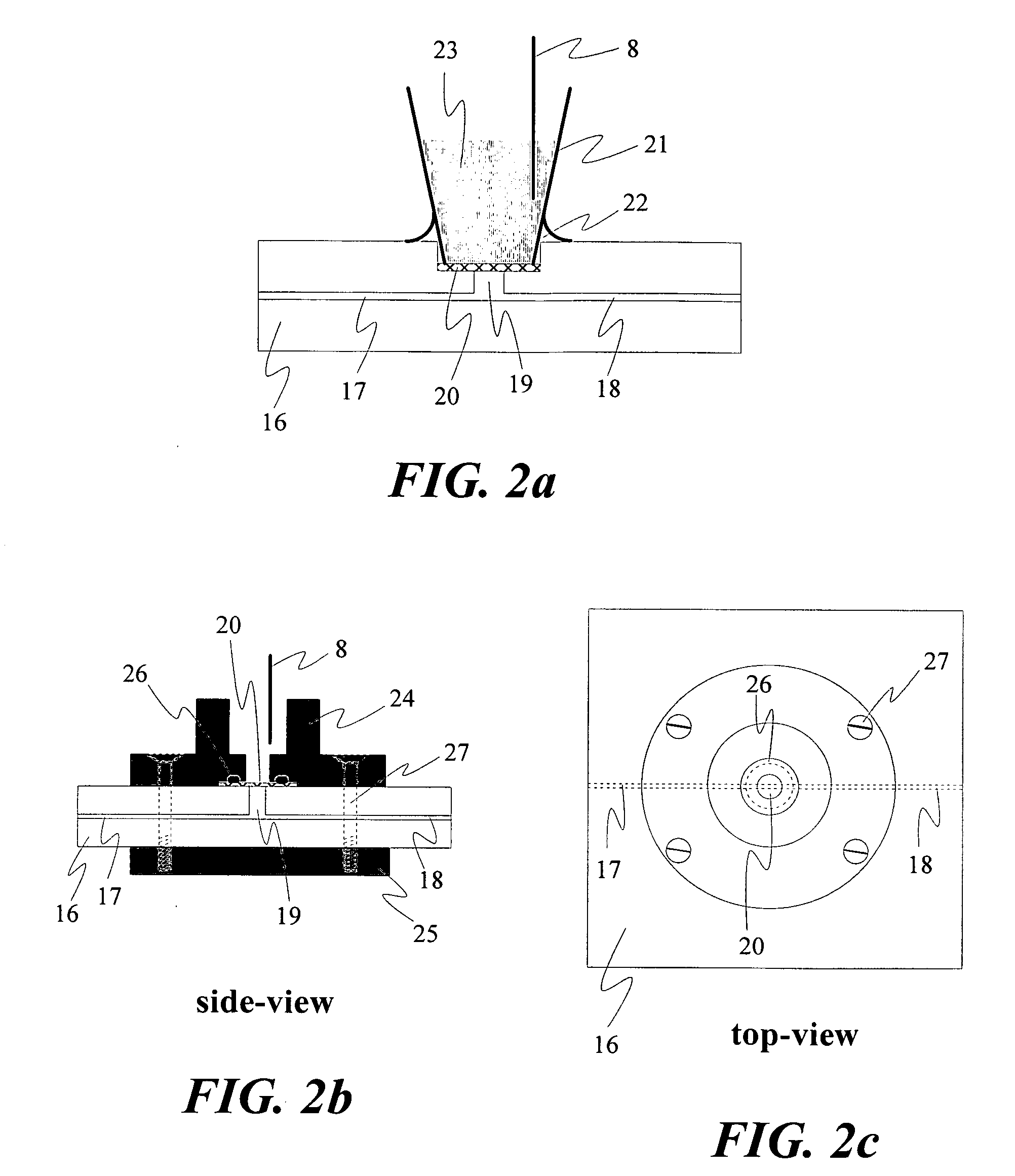
[0058] Schematic diagrams showing preferred embodiments of the small volume fluid manipulation and transportation devices of the present invention are provided in FIGS. 1 through 8. A variety of methods known in the art may be used to make and use the claimed fixed-volume-injectors. For example, the chip microfabrication protocols disclosed in Analytical Chemistry 71 (1999) 566-573, or their equivalents known in the art are readily be adapted to produce the chip component of the hybrid apparatus of the present invention.

[0059] Alternative methods known in the art may be employed within the scope of the present invention. For example, for photolithograpy a thin sacrificial layer of Cr / Au (300 Å Cr and 0.5 μm Au) may be deposited onto a glass wafer, followed by photoresist coating (Shipley photoresist 1818). After soft baking at 80 C°, the photoresist may be exposed to UV radiation through a mask. The mask pattern will be transferred to the wafer after...

example 2

Preparation of an Immobilized Polymer Coupler

[0061] A piece of bare capillary (150-μm-id, 375-μm-od and 50-cm-long) is flushed with 1 M NaOH for 45 min, ultra-pure water and acetonitrile for 15 min each, and then dried with helium. A solution of 0.4% (vol / vol) of 3-(trimethoxysilyl) propyl methacrylate and 0.2% (vol / vol) acetic acid in acetonitrile is flushed into the dried capillary with a syringe pump at 50 μl / min for 1 h. The capillary is then rinsed with acetonitrile and dried with helium. The bi-functionalized capillary is cut into desired lengths (e.g. 5 cm) for the immobilization of polyacrylamide.

[0062] 5 mL solution containing 4% (w / v) of acrylamide and a small amount (e.g. 0.003%) of N, N′-methylene-bis-acrylamide (Bis) is purged with helium for about 30 min. Then, 2 μL of 10% APS and 2 μL of TEMED are added to the solution using micro-syringes. Mixing is carried out automatically as the purging helium bubbled up. Promptly (<5 s) after the APS and TEMED are mixed with ac...


PUM

PropertyMeasurementUnit
Fractionaaaaaaaaaa
Fractionaaaaaaaaaa
Pressureaaaaaaaaaa

Abstract

A microfluidic system has an electroosmotic flow pumping means for propelling fluids through a series of microchannels and selection valves. Pump channels are configured in groups which may be fabricated singly or in multiple groups onto a substrate. A tube filled with an immobilized polymer provides a means to apply voltages across pump channels, while prevents passages of fluids through it. It also avoids electrolysis and bubble formation in or close to the microfluidic channels. The selection valves provide for routing functions within the microfluidic system and can also be configured to route fluids outside the system. A rate monitoring system is provided for determining and compensating for flow rates. In one application the microfluidic system may be configured to operate as a small volume pipettor or other fluid transport or analysis device. A micro-dialysis jacket is additionally provided to permit desalting, pH adjustment, concentration adjustment, and other functions.

Description

CROSS REFERENCE TO RELATED APPLICATIONS [0001] This application is a continuation-in-part application of U.S. patent application Ser. No. 10 / 076,170 filed Feb. 11, 2002, now abandoned, which claimed the benefit under 35 U.S.C. § 119(e) of U.S. provisional patent application Ser. No. 60 / 267,474, filed on Feb. 9, 2001, and Ser. No. 60 / 278,508, filed on Mar. 23, 2001.BACKGROUND OF THE INVENTION [0002] 1. Field of the Invention [0003] The present invention generally concerns miniature instrumentation for the facilitation of chemical reactions and the analytical separation of chemical solutions. More specifically, this invention concerns the manipulation of fluids in microfluidic chips and transportation of fluids between external devices and microfluidic chips for the facilitation of chemical reactions and the analytical separation of chemical solutions. In particular this invention provides a reliable and functionally versatile microfabricated electroosmotic flow pump with integrated m...

Claims


Application Information

Patent Timeline
IPC IPC(8): B01D61/28B01D61/56B01L3/00B01L3/02B01L99/00B81B1/00G01N1/00G01N1/34G01N27/447G01N35/00G01N35/10
CPCB01D61/28B01L99/00B01L3/0241B01L3/0268B01L3/0293B01L3/502715B01L3/50273B01L2400/0415G01N27/44743G01N27/44791G01N35/1016G01N2001/4016G01N2035/00158G01N2035/00247G01N2035/1032B01D61/56B01L13/02
Inventor LIU, SHAORONGLU, JUAN
Owner LIU SHAORONG
Learn More