
Fibril solar cell and method of manufacture

a solar cell and fuselage technology, applied in the field of fuselage solar cells, can solve the problems of low photo-conversion efficiency, high cost of single-crystalline silicon solar cells, and limited use, and achieve high photo-conversion efficiency, low manufacturing cost, and good formability.

Inactive Publication Date: 2005-09-08
SAMSUNG SDI CO LTD
View PDF4 Cites 27 Cited by
  • Summary
  • Abstract
  • Description
  • Claims
  • Application Information

AI Technical Summary

Benefits of technology

[0016] The present invention provides a fibril wet solar cell containing carbon nanotubes and having advantages of low manufacturing costs, high photo-conversion efficiencies, and a good formability, and a method of manufacturing the solar cell.

Problems solved by technology

However, since the single-crystalline silicon solar cell is very expensive, it is utilized only for special purposes, such as the aerospace industry.
A relatively inexpensive amorphous silicon solar cell is available for use, but has a low photo-converting efficiency.
A compound semiconductor solar cell comprising CuInSe2, CdTe, GaAs, and derivatives thereof has relatively good characteristics, but its use is very limited because of high cost, low efficiency, and low stability.
However, the wet solar cell cannot use light energy lower than Eg.
Consequently, the efficiency of such a wet solar cell is very low.
Since a space is formed between glass or plastic plates by a spacer in the solar cell, and the solar cell is sealed, it is difficult to manufacture the solar cell, which increases manufacturing costs.
Also, since a generated voltage is very low (about 0.7 volts), there are some limitations for commercializing the solar cell.
Since the solar cell utilizes a glass fiber, it is necessary to coat a semiconductor and an electrode having a high melting point, thereby increasing costs.

Method used


Image

  • Fibril solar cell and method of manufacture
  • Fibril solar cell and method of manufacture
  • Fibril solar cell and method of manufacture

Examples


example embodiment 1

Production of Fibril Wet Solar Cell

[0067] A. Production of Fiber

[0068] 1 gram of multiple-wall carbon nanotubes (a product commercially available from CarboLex Inc.), 3 grams of tin oxide (a product commercially available from Aldrich Corporation) with a diameter of 10 nm, and 5 grams of ammonium carbonate were mixed with 91 grams of polyvinyl alcohol (containing water in a concentration of 80 wt. %) to prepare a solution for making a fiber. The solution was spun through a wet spinning to produce a fiber with a thickness of 500 um. Then, the fiber was heat-treated at a temperature of 430° C. for 30 minutes.

[0069] B. Impregnation of Photosensitive Dye

[0070] The porous fiber produced in process A was impregnated with a solution consisting of 1 gram of multiple-walled carbon nanotubes (a product commercially available from CarboLex Inc.), 72 grams of porous titanium dioxide (a product commercially available from Nano Co. Ltd.) with a diameter of 10 nm and a surface area of 250 m2 / g...


PUM

PropertyMeasurementUnit
diameteraaaaaaaaaa
diameteraaaaaaaaaa
grain sizeaaaaaaaaaa

Abstract

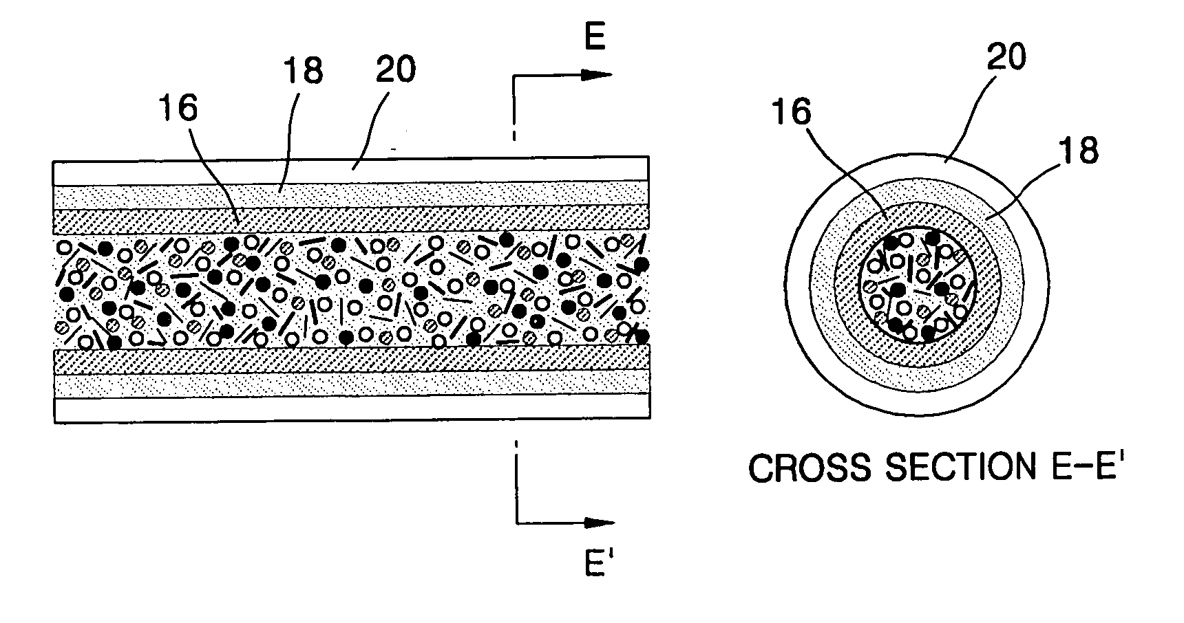
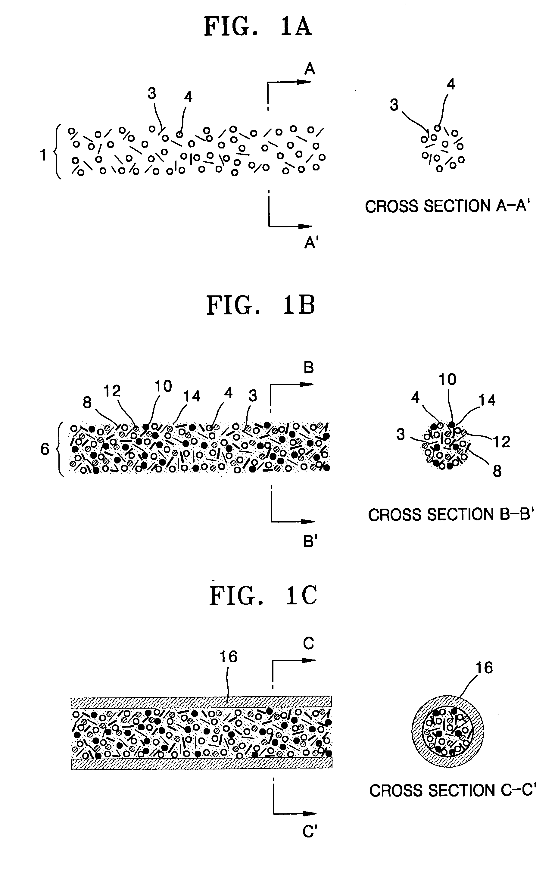
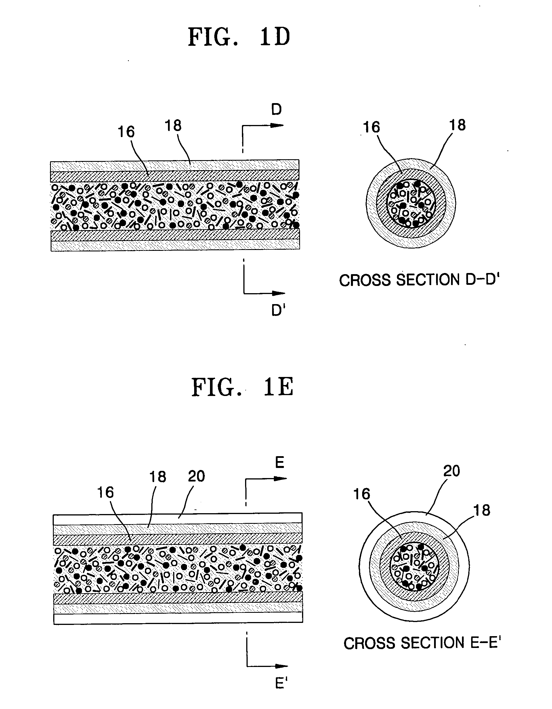
A fibril solar cell includes: a fiber-shaped inner core having a porous fiber composed of first carbon nanotubes and a cathode material, in which pores of the porous fiber are filled with second carbon nanotubes, titanium dioxide, a photosensitive dye, and an electron transfer electrolyte; a photoconductive layer formed on a surface of the fiber-shaped inner core and composed of at least one photoconductive polymer; a transparent electrode layer formed on a surface of the photoconductive layer; and a transparent protective layer formed on a surface of the transparent electrode layer and composed of at least one transparent polymer. The fibril solar cell can be mass-produced inexpensively using a polymer. Also, the fibril solar cell has a high efficiency and can be converted into various shapes. The fibril solar cell can be attached to clothing, and be used as a portable power source for mobile electronics.

Description

CLAIM OF PRIORITY [0001] This application makes reference to, incorporates the same herein, and claims all benefits accruing under 35 U.S.C. §119 from an application for FIBRIL SOLAR CELL AND METHOD OF MANUFACTURING THE SAME earlier filed in the Korean Intellectual Property Office on 28 Jan. 2004 and there duly assigned Ser. No. 10-2004-0005316. BACKGROUND OF THE INVENTION [0002] 1. Field of the Invention [0003] The present invention relates to a solar cell and a method of manufacturing the solar cell, and more particularly, to a fibril wet solar cell containing carbon nanotubes and having low manufacturing costs, high photo-conversion efficiency, and a good formability, and a method of manufacturing the solar cell. [0004] 2. Description of the Related Art [0005] As global concerns about polluting energy sources increase, interest in alternative energy sources to fossil fuels, such as coal or petroleum, has increased. For example, a solar cell is a device for converting solar energy...

Claims


Application Information

Patent Timeline
Patent Type & Authority Applications(United States)
IPC IPC(8): H01L31/04H01G9/20H01L31/00H01L31/042H01M14/00H10K99/00
CPCB82Y10/00H01G9/2031H01G9/2068H01G9/2086H01L27/304Y02E10/549H01L51/0052H01L51/0086H01L51/4226Y02E10/542H01L51/0048Y02P70/50H10K30/53H10K85/221H10K85/615H10K85/344H01G9/20H01L31/04H01L31/18H10K30/151
Inventor JIN, YONG-WANKIM, JONG-MIN
Owner SAMSUNG SDI CO LTD
Learn More