Liquid crystal display element and manufacturing method thereof

a technology of liquid crystal display element and manufacturing method, which is applied in the direction of optics, instruments, non-linear optics, etc., can solve the problems of large amount of paper consumed mainly in offices, consumption of paper meant for short-lived documentation, and information consumption has tended to increase more, so as to achieve superior threshold steepness and superior display

Inactive Publication Date: 2005-09-15
FUJIFILM BUSINESS INNOVATION CORP
View PDF5 Cites 13 Cited by
  • Summary
  • Abstract
  • Description
  • Claims
  • Application Information

AI Technical Summary

Benefits of technology

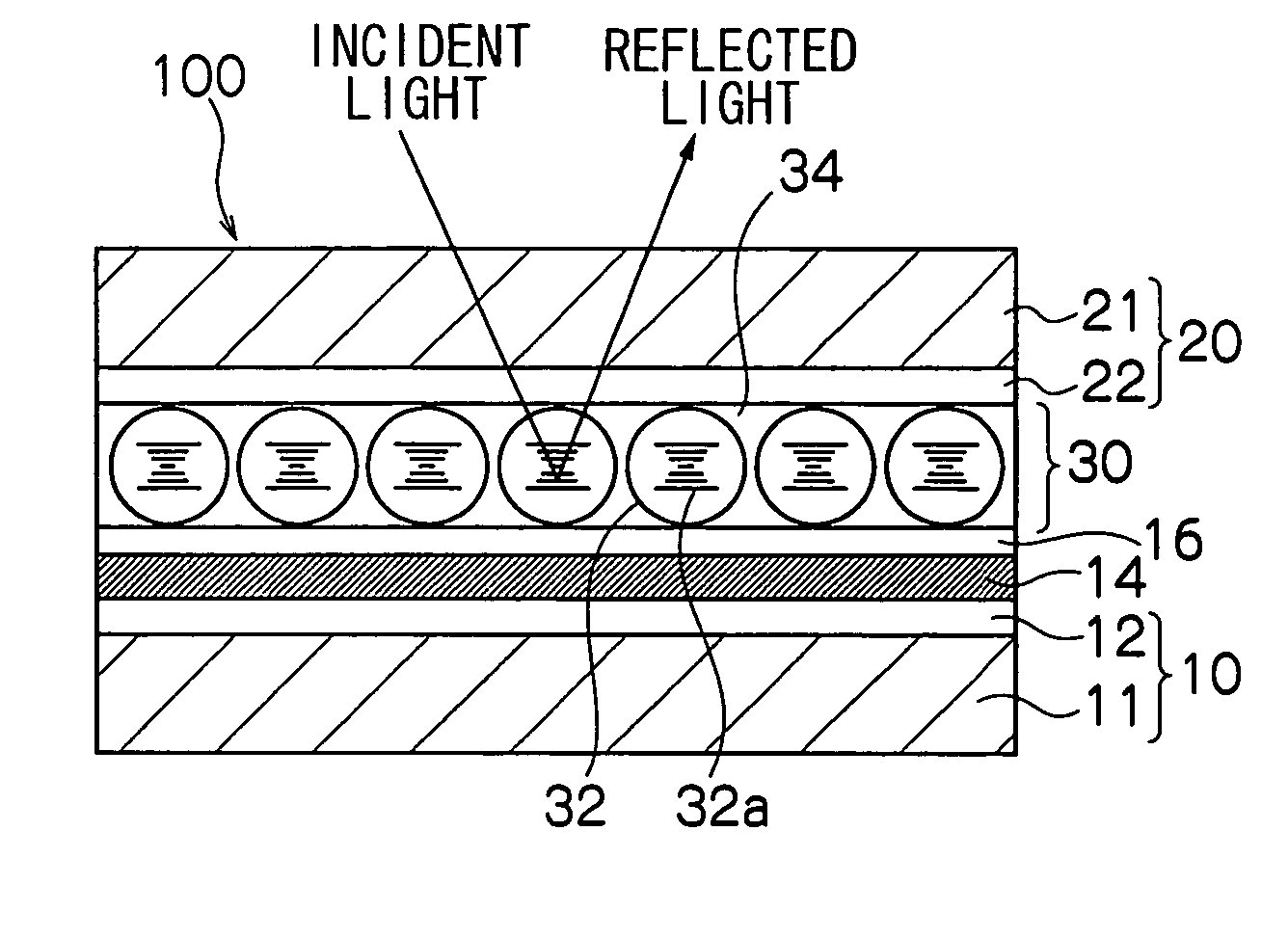
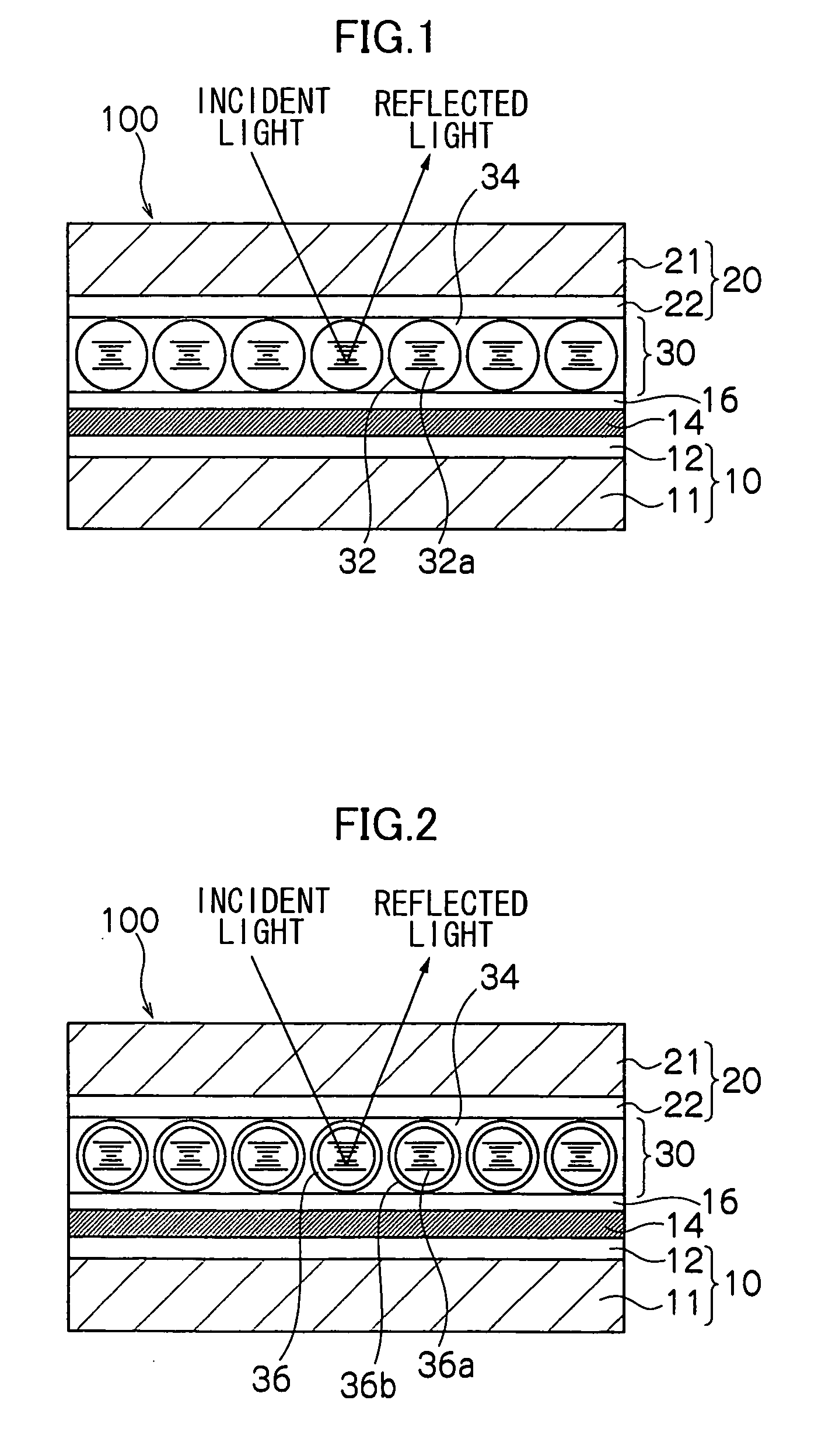
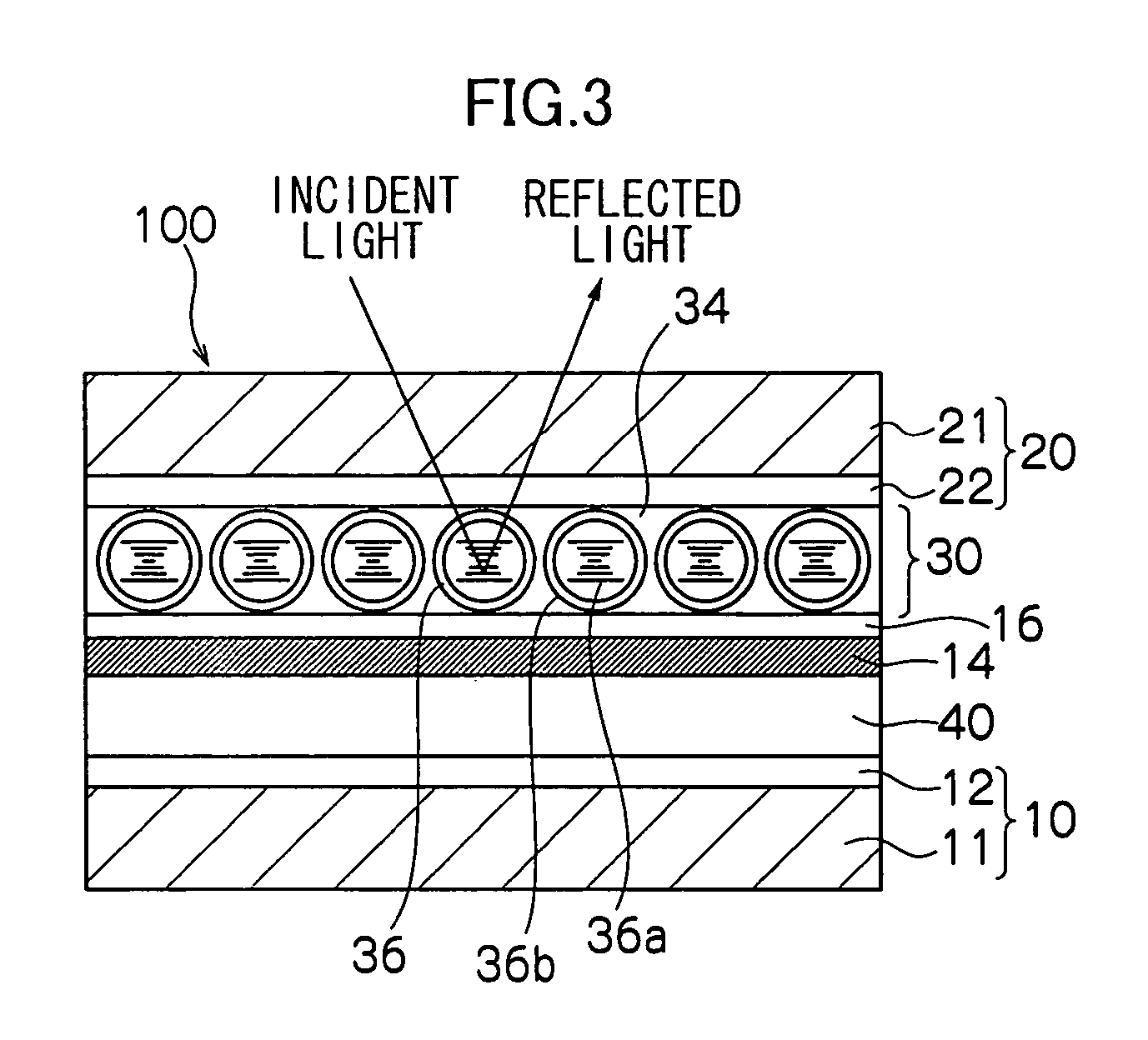
[0030] With regard to the liquid crystal display element of the invention, monodispersed liquid crystal drops or liquid crystal microcapsules are densely arrayed in a monolayer and the surface of the display layer is flat, whereby the problem can be avoided which arises in a case where polydispersed liquid crystal drops or liquid crystal microcapsules conventionally having a curved interface such as a spherical or elliptical shape are arrayed in multilayers and surface irregularities of a display layer are large. That is, the use of cholesteric liquid crystal as

Problems solved by technology

The large quantity of paper consumed mainly in offices has become problematic, owing to both the destruction of forest resources to obtain the raw material for paper pulp as well as environmental pollution arising from the disposal and incineration of refuse.
However, consumption of paper meant to be short-lived documentation for temporary viewing of electronic information has tended to increase more and more with the spread of personal computers and the development of information-based society, as with the Internet.
However, a cholesteric liquid crystal display element having a PDLC or PDMLC structure has problems in that selective reflection color in the planar state is low in brightness and color purity so as not to allow a clear color display, and that light transmittance in the focal conic state is poor such that contrast decreases due to a turbid black display in a display element provided with a black light-absorbing layer on the back thereof.
This also results in unnecessary scattered light in the focal conic state.
However, the problem arises of surface irregularities of a display layer becoming large due to the enlarged liquid crystal drops as described below.
Drying progresses in a state where individual dispersed liquid crystal drops cannot freely move, and thus the obtained display la

Method used


Image

  • Liquid crystal display element and manufacturing method thereof
  • Liquid crystal display element and manufacturing method thereof
  • Liquid crystal display element and manufacturing method thereof

Examples


example 1

Preparation of Coating Solution for Display Layer

[0098] 77.5 mass % of nematic liquid crystal (E7 (trade name) manufactured by Merck & Co., Inc.), 18.8 mass % of a chiral agent 1 (CB15 (trade name) manufactured by Merck & Co., Inc.) and 3.7 mass % of a chiral agent 2 (R1011 (trade name) manufactured by Merck & Co., Inc.) are mixed to prepare cholesteric liquid crystal that selectively reflects light of green color.

[0099] The cholesteric liquid crystal is emulsified in a 0.25 mass % aqueous solution of sodium dodecylbenzenesulfonate at a nitrogen pressure of 0.12 kgf / cm2 with a membrane emulsification device (MICRO KIT (trade name) manufactured by SPG TECHNOLOGY Co., Ltd.) which includes a ceramic porous film having a pore side of 4.2 μm. The state of dispersion of the resultant emulsion, which includes cholesteric liquid crystal drops haing an average size of 14.9 μm and a size standard deviation of 1.32 μm, is close to monodisperse.

[0100] Next, the emulsion is allowed to stand ...

example 2

[0121] A cholesteric liquid crystal emulsion is prepared in the same manner as in Example 1. A water-soluble melamine-formalin resin (MX-035 (trade name) manufactured by Sanwa Chemical Industries, Ltd.) is added thereto such that the amount of the resin is one fifth of that of the cholesteric liquid crystal in terms of part by mass. They are reacted at 65° C. for 3 hours to obtain a slurry including microcapsules each of which has a shell made of the melamine-formalin resin and encapsulating the cholesteric liquid crystal. The average size of the microcapsules is 15.2 μm.

[0122] Next, the slurry is allowed to stand so as to the microcapsules to settle. The resultant supernatant is removed to obtain a condensed slurry. The ratio of volume of the microcapsules to that of the condensed slurry is measured with a densitometer (DMA35n (trade name) manufactured by Nihon SiberHegner K.K.) and found to be 0.482.

[0123] The ratio AL of an area covered by the liquid crystal micrcapsules to a c...

example 3

[0129] An adduct (Takenate D110N (trade name) manufactured by Takeda Chemical Industries, Ltd.) of xylene diisocyanate to trimethylolpropane at a ratio of 3:1 and ethyl acetate are added to the same cholesteric liquid crystal as in Example 1 so that the amount of each of these components is one fifth of that of the cholesteric liquid crystal in terms of part by mass. The resultant is stirred to obtain a uniform solution serving as an oil phase.

[0130] One part by mass of ethyl acetate is added to 10 parts by mass of a 1.0 mass % aqueous solution of partially saponified PVA having a polymerization degree of 500 and manufactured by Wako Pure Chemical Industries, Ltd., and the resultant is stirred at 70° C. and then cooled down to room temperature. Another uniform solution serving as an aqueous phase is obtained by removing a part of ethyl acetate which part has not been dissolved.

[0131] The oil phase is emulsified in the aqueous phase at a nitrogen pressure of 0.10 kgf / cm2 with a mem...


PUM

PropertyMeasurementUnit
Temperatureaaaaaaaaaa
Timeaaaaaaaaaa
Sizeaaaaaaaaaa

Abstract

The invention discloses a liquid crystal display element including: a pair of display substrates each having a support and an electrode provided on one surface of the support; and a display layer provided between the electrodes of the pair of display substrates, wherein the display layer contains gelatin and liquid crystal drops or microcapsules; and the liquid crystal drops or microcapsules are densely arrayed in a monolayer, and a method of manufacturing the liquid crystal display element, including: applying to a surface of one of the display substrates which surface has the electrode, a coating solution in which liquid crystal drops or microcapsules are dispersed in a solution containing gelatin and a solvent, thereby forming a coating layer; and evaporating the solvent in the coating layer at a temperature not less than the freezing point of the gelatin to provide a display layer between the electrodes of the display substrates.

Description

CROSS-REFERENCE TO RELATED APPLICATION [0001] This application claims priority under 35 USC 119 from Japanese Patent Application No. 2004-72928, the disclosure of which is incorporated by reference herein. BACKGROUND OF THE INVENTION [0002] 1. Field of the Invention [0003] The present invention relates to a liquid crystal display element having a display layer including liquid crystal drops or liquid crystal microcapsules, and a manufacturing method thereof. [0004] 2. Description of the Related Art [0005] The large quantity of paper consumed mainly in offices has become problematic, owing to both the destruction of forest resources to obtain the raw material for paper pulp as well as environmental pollution arising from the disposal and incineration of refuse. However, consumption of paper meant to be short-lived documentation for temporary viewing of electronic information has tended to increase more and more with the spread of personal computers and the development of information-...

Claims


Application Information

Patent Timeline
IPC IPC(8): G02F1/139G02F1/1333G02F1/1334
CPCG02F1/13718G02F1/1334
Inventor HARADA, HARUOARISAWA, HIROSHI
Owner FUJIFILM BUSINESS INNOVATION CORP
Why Eureka
Try Eureka