
Optical recording material, optical recording medium and optical recording/reproducing apparatus

Inactive Publication Date: 2005-09-22
FUJIFILM BUSINESS INNOVATION CORP
View PDF12 Cites 23 Cited by
  • Summary
  • Abstract
  • Description
  • Claims
  • Application Information

AI Technical Summary

Benefits of technology

[0021] The present invention has been made in view of the above-described circumstances and provides an optical recording material that is able to maintain high recording sensitivity, wide dynamic range and high diffraction efficiency by controlling the length of side chain spacers in order to increase the thickness of the film. The invention also provides an optical recording medium capable of larger recording capacity by increasing the thickness of a photosensitive layer without impairing recording property. The invention further provides an optical recording / reproducing apparatus having large data capacity.
[0025] The invention provides an optical recording material maintaining high recording sensitivity, wide dynamic range and high diffraction efficiency in order to increase the thickness of the film. The invention also provides an optical recording medium capable of large capacity recording without impairing recording property, and an optical recording / reproducing apparatus capable of recording and reproducing large capacity data.

Problems solved by technology

Although these materials exhibit a light-induced refractive index changing effect (photorefractive effect) with high sensitivity and high efficiency, they exhibit such defects that crystal growth thereof is often difficult, machining into a desired shape is impossible since most of these materials are hard and fragile, and adjustment of sensitive wavelength is difficult.
However, this organic PR material has a problem in that it is essential to apply an outer electric field.
Since the electric field is as large as several hundred V·mm−1, this is a large restriction on the apparatus when utilizing such a system as a recording apparatus.
Moreover, since various different materials such as the charge generating material, charge transfer material and polymer substrate are used in combination, a decrease in stability due to phase separation during recording or preservation is another large problem.
While a holographic recording material using an azobenene-containing polymer having azobenzene site of a specified structure in a side chain and having a main chain of an acrylate or methacrylate structure has been disclosed with respect to the materials above, the material still has the problems described below.
Since forming a thick recording medium for realizing a high diffraction efficiency is difficult, the polymer is insufficient as a material for an optical recording material having high recording density and high sensitivity (see, for example, Japanese National Publication Nos. 2000-514468 and 2002-539476, U.S. Pat. No. 6,441,113 B1 and Japanese Patent Application Laid-Open (JP-A) No. 10-212324).
Accordingly, it has been difficult for the conventional azobenzene-containing polymer materials to form a thick medium for use as a three-dimensional hologram material for forming plural holograms in the optical recording material, or to achieve high speed recording of digital data by realizing a high diffraction efficiency.
The magnitude of modulation of the refractive index for forming the hologram is restricted by the ability of medium materials.
While selecting a wavelength having a high absorption is effective for improving recording sensitivity, other problems also occur.
It is known that angular selectivity of the diffraction efficiency is deteriorated when the amplitude of the refractive index of the hologram is attenuated in the thickness direction.
Furthermore, realizing a high diffraction efficiency becomes difficult due to absorption loss of the medium.
Accordingly, it has been difficult to make high sensitivity compatible with a high dynamic range.

Method used


Image

  • Optical recording material, optical recording medium and optical recording/reproducing apparatus
  • Optical recording material, optical recording medium and optical recording/reproducing apparatus
  • Optical recording material, optical recording medium and optical recording/reproducing apparatus

Examples


examples

[0125] The present invention will be described in detail below with reference to examples. However, the following examples should not be construed to limit the scope of the invention.

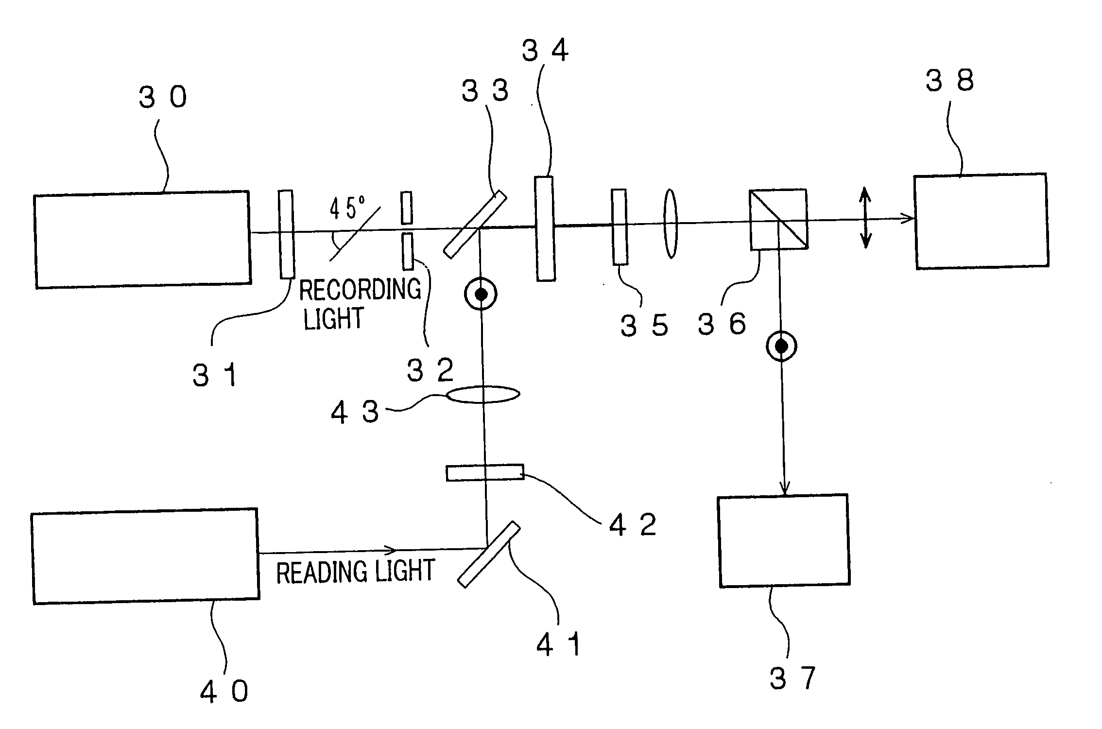
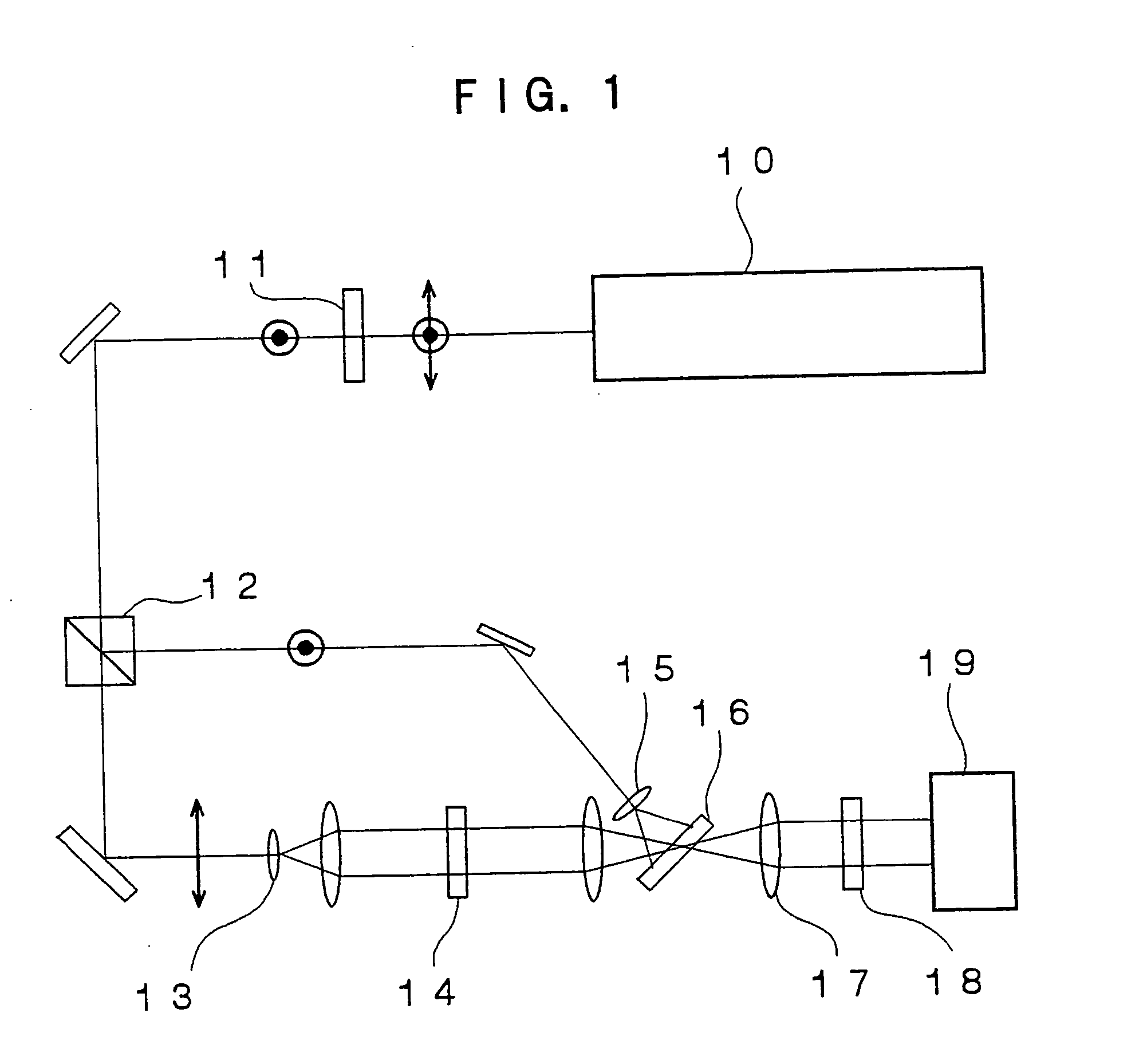
[0126] An optical recording material of the invention having spacers of the photoresponsive side chains shorter than spacers of the non-photoresponsive side chains is synthesized, and the optical recording material is compared with conventional optical recording materials in the optical recording medium and in the optical recording / reproducing apparatus using the optical recording medium.

(Synthesis of Photoresponsive Polyester)

—Photoresponsive Polyester 1 (Optical Recording Material of the Invention)—

[0127] Mixed in a 300 ml three-necked flask equipped with a vacuum evacuator and stirrer are 0.003 mol of diethyl 5{6-[4-(4-methylphenylazo)phenoxy]butyloxy}isophthalate (photoresponsive dicarboxylic acid monomer carrying methylazobenzene), 0.007 mol of diethyl 5-{6-[4-(4-cyanophenyl)phenoxy]hexyloxy}is...


PUM


Abstract

An optical recording material which includes at least one of a polymer and an oligomer, the at least one of a polymer and an oligomer comprising a photoresponsive group. The optical recording material records information through change in at least one of absorption, refractive index and shape due to irradiation of light thereto. A main chain of the at least one of a polymer and an oligomer has a side chain comprising a mesogenic unit linked thereto. The side chain comprises at least two flexible spacer groups introduced thereto, the spacer groups having lengths different from each other.

Description

CROSS-REFERENCE TO RELATED APPLICATION [0001] This application claims priority under 35USC 119 from Japanese Patent Application No. 2004-83716, the disclosure of which is incorporated by reference herein. BACKGROUND OF THE INVENTION [0002] 1. Field of the invention [0003] The present invention relates to an optical recording material, an optical recording medium and an optical recording / reproducing apparatus, particularly to a three-dimensional optical recording medium having a large storage capacity, an optical recording material used for the optical recording medium, and an optical recording / reproducing apparatus for recording and reproducing information using the optical recording medium. [0004] 2. Description of the Related Art [0005] Conventional optical disk storage apparatus has been devised to reduce the distance between adjoining tracks or pits by reducing the diameter of beam spots in order to enhance recording density. However, since the distance has approached a physical...

Claims


Application Information

Patent Timeline
IPC IPC(8): G03C1/73G03H1/02G11B7/0065G11B7/24G11B7/245G11C13/04
CPCG03H1/0244G03H2001/0264G11C13/045G11B7/245G11B7/0065
Inventor MINABE, JIROMARUYAMA, TATSUYATAKIZAWA, HIROO
Owner FUJIFILM BUSINESS INNOVATION CORP
Learn More