
Method and apparatus for a monodiameter wellbore, monodiameter casing, monobore, and/or monowell

a technology of monodiameter casing and monowell, which is applied in the direction of directional drilling, borehole/well accessories, survey, etc., can solve the problems of substantial reduction of the diameter of the wellbore, inability to usefully complete the well, and reduced the delivery capacity of the well, so as to reduce the number and size of the casing strings, reduce the size of the borehole, and achieve design optimization and efficiencies

Inactive Publication Date: 2005-11-03
HALLIBURTON ENERGY SERVICES INC
View PDF99 Cites 90 Cited by
  • Summary
  • Abstract
  • Description
  • Claims
  • Application Information

AI Technical Summary

Benefits of technology

[0062] The present invention achieves design optimization and efficiencies by reducing borehole size utilizing expandable casing and / or chemical casing. The use of expandable casing and / or chemical casing reduces the number and size of casing strings thereby reducing the materials required to drill and complete a monodiameter well. Also the number and size of high pressure risers may be reduced in a deep water well. Expandable casing also permits cladding or sealing, and chemical casing permits the use of sealants. The expandable casing allows the consolidation of conventional casings strings and operations. By utilizing expandable casing, additional borehole size is not reduced which otherwise would be required for casing hangers, annular spacing between casing strings, and float shoes. Still further, the cladding of the adjacent sections of expandable casing eliminates large bulky liner hangers, which otherwise require additional borehole diameter utilization. Expandable liner hangers can be utilized. The monodiameter well architecture, however, will not require the liner to have a larger diameter supporting. Of course, larger diameter casing requires not only a greater amount of drilling fluid to drill the borehole but also a larger amount of cement to cement the casing in the borehole.
[0063] The MONOWELL architecture has several unique features and advantages over the traditional well construction architecture. The methods and apparatus of the present invention form a monodiameter wellbore in the well reducing overall borehole dimensions. Thus the MONOWELL minimizes fluid requirements and volumes, equipment size / volumes, and materials required in the hydrocarbon, gas, water businesses, and / or any other drilling and production business. It utilizes less drilling fluids and cement. The drilling fluids and cement required for the well are reduced because large diameter boreholes and large diameter casing are not required. These are particularly advantageous in deep water wells where equipment size and fluid volumes must be optimized due to high cost. It reduces the amount of earth cut and thus reduces the cuttings generated. It has less environmental impact than a conventional wellbore by reducing the materials utilized, the earth contacted, the materials disposed, and the energy consumed during the well construction process.
[0064] Reducing the materials provides many advantages. Less drilling fluid and cement are required, drilling time is reduced, and smaller fluid volume and horsepower capacity rigs may be used. Still further, bulk storage on location is eliminated and horse power requirements are substantially reduced.
[0065] In reducing overall borehole dimensions, conventional casings, liners and tubing, as well as risers in subsea wells, are reduced in size or are eliminated. The monodiameter casing eliminates the series of nested different diameter casings. In a subsea well, instead of having a 36 inch conductor casing, the conductor casing may be 17 to 18 inches. The drilling blowout preventer is reduced from the standard 18¾ inch BOP to a 13⅝ inch BOP. The diameter of the riser extending from the ocean floor to the surface is also reduced. The number and size of surface and intermediate casings and high pressure risers may be reduced in a deep water well. The size of the hangers are reduced. It utilizes a smaller wellhead, casing, and risers for the final reservoir penetration.
[0066] MONOWELL architecture also allows the reduction in equipment size permitting the use of a small drilling rig, workover rig, or well intervention device. The methods and apparatus of the present invention allow the use such that a smaller, less sophisticated offshore rig, such as a second or third generation rig, may be used to drill the well rather than a fifth or sixth generation rig that handles larger boreholes and casing in the case of deepwater operations. Smaller land rigs may also be used particularly in horizontal and long extended reach wells.

Problems solved by technology

If the driller encounters an extended series of high pressure / low pressure intervals, the number of liners required under such circumstances may be such that the well cannot usefully be completed because of the continued reduction of the casing diameters required.
Along with the downsize serial casing operations, the production tubulars may have to be downsized as well further reducing the delivery capacity of the well.
The casing insert may not be possible, requiring that the well be sidetracked, resulting in a substantial reduced diameter wellbore.
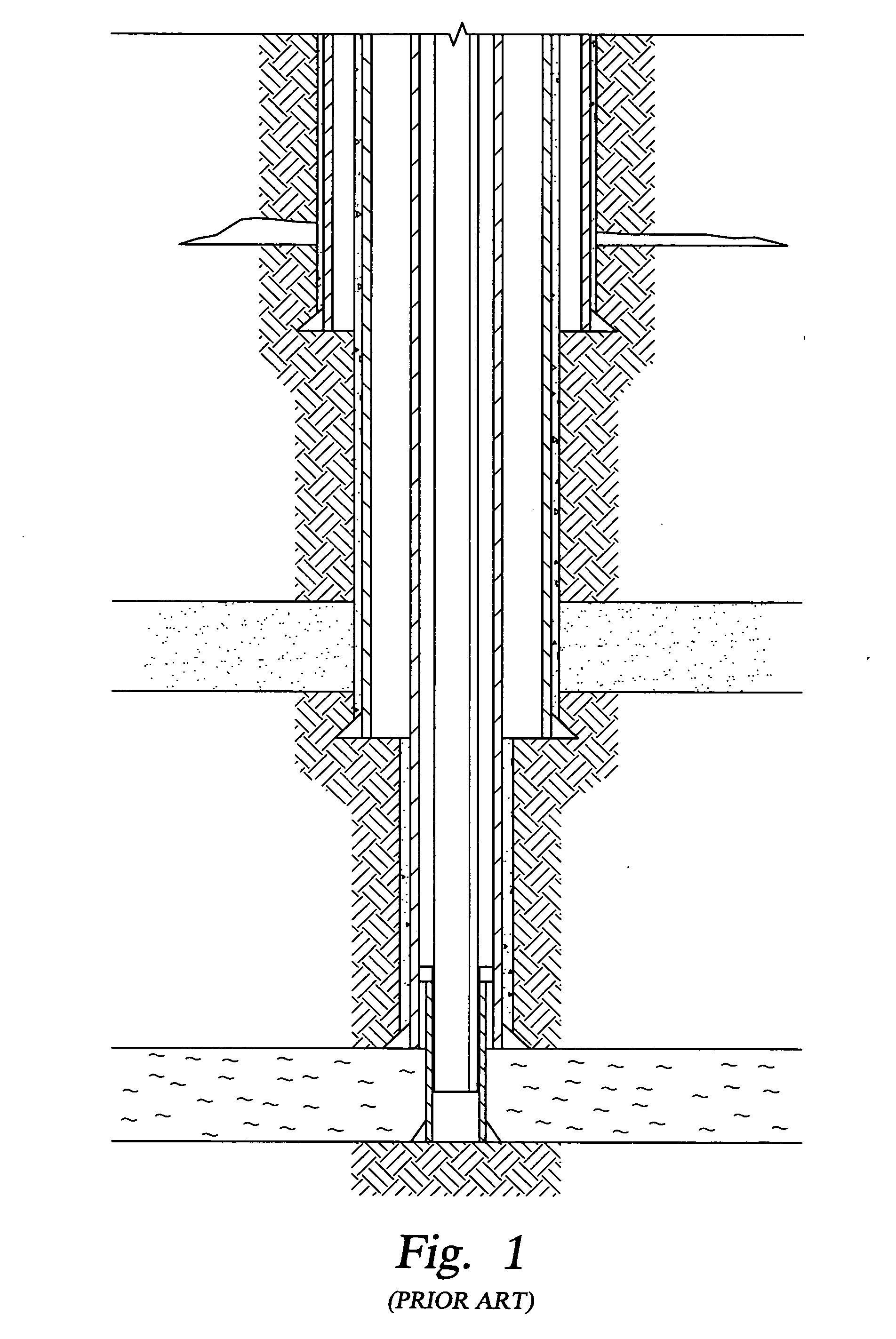
The disadvantages of nesting casing and liners is apparent in slim-hole drilling.
Over time, the formation may collapse and settle against the outer wall of the liner so that the area around the liner gets filled with particulates.
A problem generally encountered during cementation of the casing is, that due to various factors, such as the existence of varying pressure and temperature gradients along the length of the casing and shrinkage of the cement body during hardening thereof, relative displacements occur between the casing and the hardened cement mass which may result in poor bonding or cracking between the cement body and the casing.
Poor bonding may result in the presence of a so-called micro-annuli between the casing and cement body, micro-annuli may extend along a substantial part of the length of the casing.
The occurrence of a micro-annuli is particularly dangerous in gas wells as substantial amounts of gas might escape to the surface.
This condition may also lead to surface or ground water contamination.
The resulting problems are very expensive to correct.
The poor bonding of the cement may be attributed to drilling fluid contamination or to bonding of the cement to the casing after the cement has set and / or oil or mill finish contamination on the surface of the casing or it can be attributed to aggressive drilling or aggressive pressure subjection and large pressure differs prior to it hardening and during the operation.
A more fundamental cause is the loss of hydrostatic head during the curing of the cement such that the formation pressure exceeds the annulus pressure and gas migration occurs causing channeling of the cement and subsequent leakage.
This technique, however, results in a lower strength cement.
These specialized cement additives are expensive and require specific operational techniques.
Further, a borehole may be drilled through the riser and wellhead and through a problematic formation to extend a structural casing through the problem formation.
Large boreholes are disadvantageous in that they generate large amounts of cuttings and require increased volumes of drilling fluid and cement.
Generally speaking, larger borehole sizes take longer to drill than smaller diameter boreholes at equivalent depth.
For example, increased drilling rig time is involved due to required cement pumping and cement hardening.
Further, a large borehole diameter often takes larger fluid and horsepower capacity rigs generating increased costs due to heavy casing handling equipment and large drill bits.
Utilizing a large borehole often causes the usage of a wide variety of equipment and fluids that might not achieve maximum efficiency for the drilled borehole.
Further, the large risers add substantial expense and additional large sized completion equipment.
The challenge to the industry is to develop the full suite of enabling and complimentary technologies that will be required to drill and complete a monodiameter well.
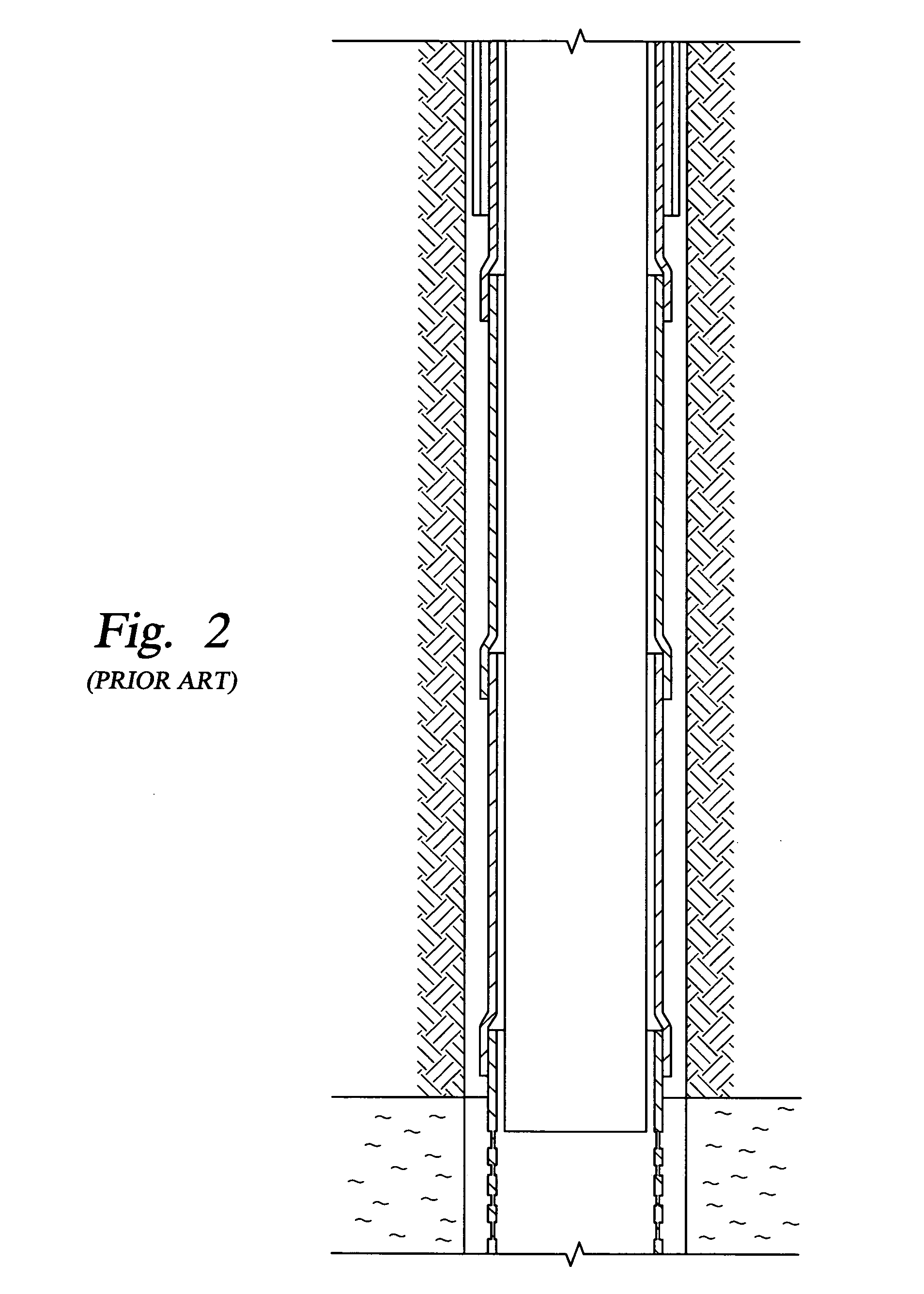
However, the collapse strength of a post expanded tubular is less than that of the pre-expanded tubular but it is within the design limits expected for the required borehole pressures.
A simple expansion of metal against metal does not provide a reliable seal.
However, cement is undesirable for use with expandable casing.
Oilfield cement or hydraulic cement compositions are incompressible and tend to resist the expansion of the casing or liner making the expansion more difficult.
Thus, expansion of the casing / liner can lead to the crushing of the cement, and consequent loss of effectiveness regarding the zones.
This problem is exacerbated by the small annular clearance associated with expandable casing / liners.
Conventional cement will be particularly brittle and weak in such thin sheaths or thicknesses and is hence an inappropriate sealing medium.
Other problems may be encountered using oilfield cement or hydraulic cement as the sealing composition for expandable casing / liners.
In a severely washed out borehole, such as soft formations with wash outs and ledges, the sealant material may not be adequate.
Thus there is a much longer time period than in conventional drilling during which the borehole wall is unsupported by casing during drilling.
Such remedial actions are time consuming and expensive.
However, in order to insure that fracturing of low mechanical strength formations penetrated by the well bore and other similar problems do not occur, it may become necessary to case and cement the borehole.
Another problem that occurs in the drilling and completion of well bores is that when the well bore is drilled into and through unconsolidated weak zones or formations.
Unstable materials such as clays, shales, sand stone and the like make up a high percentage of the formations in which wells are drilled, and a majority of well bore problems are a result of the instability of such materials, particularly shale instability.
Such shales upon contact with aqueous drilling fluids swell and fracture rendering the well bore wall unstable.
Sloughing of shale and other similar unstable materials into the well bore can cause the drill string to become stuck and can enlarge the well bore resulting in large subterranean cavities.
Additionally, when sloughing occurs while the drill bit is being changed at the surface, the well bore fills up and must be cleared before drilling can proceed.
Furthermore, the heaving unstable material suspended in the drilling fluid increases its solid content, and as a result, the viscosity of the drilling fluid increases to the point where the drilling fluid must be chemically treated to reduce its viscosity or it must be diluted followed by the addition of weighting material to maintain its mud weight.
The instability of clays, shales, sand stone and the like is also caused by hydraulic pressure differential leading to fluid transport and by pressure changes near the well bore as the drilling fluid compresses pore fluid and diffuses a pressure front into the formation.
Such fractures cause drilling fluid to be lost and also require stoppage of the drilling operation and costly remedial steps to be taken.
Each restriction in the completion tubulars causes a pressure drop across that point causing scale and corrosion to occur at these points.
The narrowing of the completion tubulars also reduces flow and therefore production.

Method used


Image

  • Method and apparatus for a monodiameter wellbore, monodiameter casing, monobore, and/or monowell
  • Method and apparatus for a monodiameter wellbore, monodiameter casing, monobore, and/or monowell
  • Method and apparatus for a monodiameter wellbore, monodiameter casing, monobore, and/or monowell

Examples


Embodiment Construction

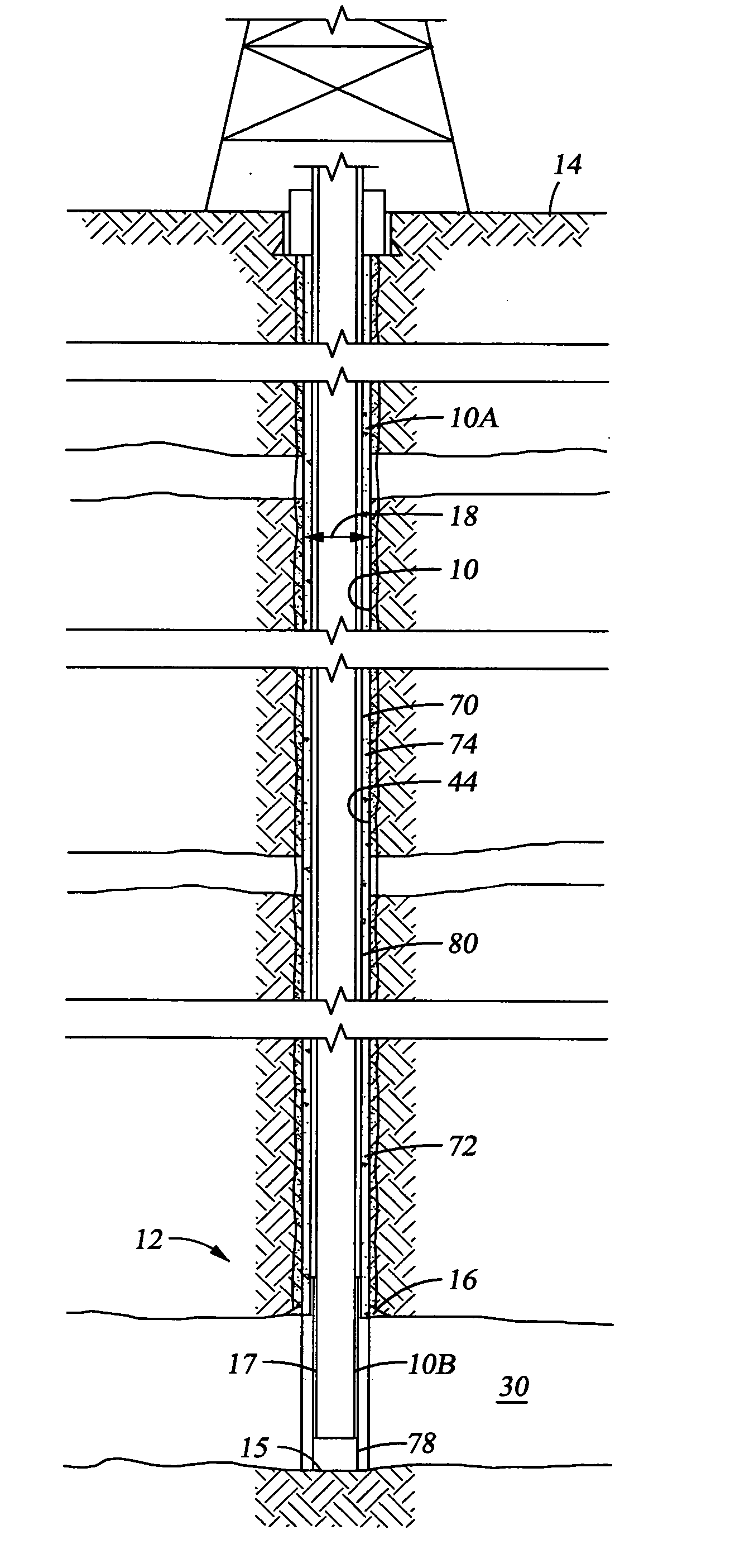
[0056] The present application is directed to a system to achieve a MONOWELL and provides a total solutions approach to the well construction of a monodiameter wellbore and MONOWELL. The assembly and methods of the present invention construct a MONOWELL having monodiameter casing and monobore throughput. The monodiameter casing is disposed in a monodiameter wellbore having diametric efficiency. The monobore is a fullbore production delivery system which either extends through the monodiameter casing from the surface to the formation barrier or extends through the monodiameter casing from the surface and through the producing formation. A full bore production delivery system will have the same nominal internal diameter throughout the production conduit no matter whether the well is an injection well or a producing well. Full bore production delivery is typically provided by production tubing. While a well may have a monodiameter architecture, it may or may not have a full bore produc...


PUM


Abstract

An assembly and methods for constructing a MONOWELL includes a monodiameter casing disposed in a monodiameter wellbore having diametric efficiency with a monobore production delivery system disposed within the monodiameter casing. An assembly for constructing a monodiameter wellbore includes a bottomhole assembly having a overgauge hole drilling member, a directional steering assembly, a measurement while drilling tool, and a logging while drilling tool; a work string attached to the bottomhole assembly and extending to the surface; drilling fluids flowing through the work string and bottomhole assembly; chemical casing casing the borehole; expandable casing disposed in the wellbore; and a sealing composition disposed between the expandable casing and the wellbore.

Description

CROSS-REFERENCE TO RELATED APPLICATIONS [0001] The present application claims the benefit of 35 U.S.C. 119(e) of U.S. provisional application Ser. No. 60 / 335,132 filed Nov. 14, 2001 and entitled Monodiameter Well Architecture and Construction and U.S. provisional patent application Ser. No. 60 / 414,517, filed Sep. 27, 2002 and entitled Method and Apparatus for a Monodiameter Wellbore, Monodiameter Casing and Monobore, both hereby incorporated herein by reference in their entirety. The present application is related to U.S. patent application Ser. No. 10 / 170,400 filed Jun. 13, 2002 and entitled Methods of Consolidating Formations or Forming Chemical Casing or Both While Drilling, now U.S. Pat. No. 6,702,044; U.S. patent application Ser. No. 10 / 006,109 filed Dec. 4, 2001 entitled Resilient Cement, now U.S. Pat. No. 6,668,928; U.S. patent application Ser. No. 10 / 177,568 filed Jun. 21, 2002 entitled Methods of Sealing Expandable Pipe in Well bores and Sealing Compositions, now U.S. Pat. ...

Claims


Application Information

Patent Timeline
IPC IPC(8): E21BE21B7/00E21B7/04E21B7/20E21B7/28E21B17/00E21B29/00E21B29/02E21B33/14E21B43/10E21B47/02E21B47/12
CPCC09K8/12C09K8/34E21B43/103E21B33/138C09K8/512E21B7/04C09K8/42E21B7/20E21B17/00E21B29/02E21B33/14E21B43/10
Inventor WYLIE, GLENDAZAMORA, FRANKMURALI, BEEGAMUDRE N.TERRY, JAMES B.BROTHERS, LANCE EVERETTPALMER, ANTHONY VANNREDDY, BAIREDDY R.EOFF, LARRY S.WEAVER, JEMMIE D.WILSON, JOHN M.BERRYHILL, DENISEFITSGERALD, RUSSELL M.CULOTTA, ANNE M.RAO, M. VIKRAMBOULTON, ROGERCHEN, CHEN-KANG DAVIDGAYNOR, THOMAS M.HARDIN, JOHNGLEITMAN, DANIELWALKER, COLIN
Owner HALLIBURTON ENERGY SERVICES INC
Learn More