
Method and apparatus for dispersion strengthened bond coats for thermal barrier coatings

Inactive Publication Date: 2005-12-29
UNIV OF VIRGINIA ALUMNI PATENTS FOUND
View PDF6 Cites 44 Cited by
  • Summary
  • Abstract
  • Description
  • Claims
  • Application Information

AI Technical Summary

Benefits of technology

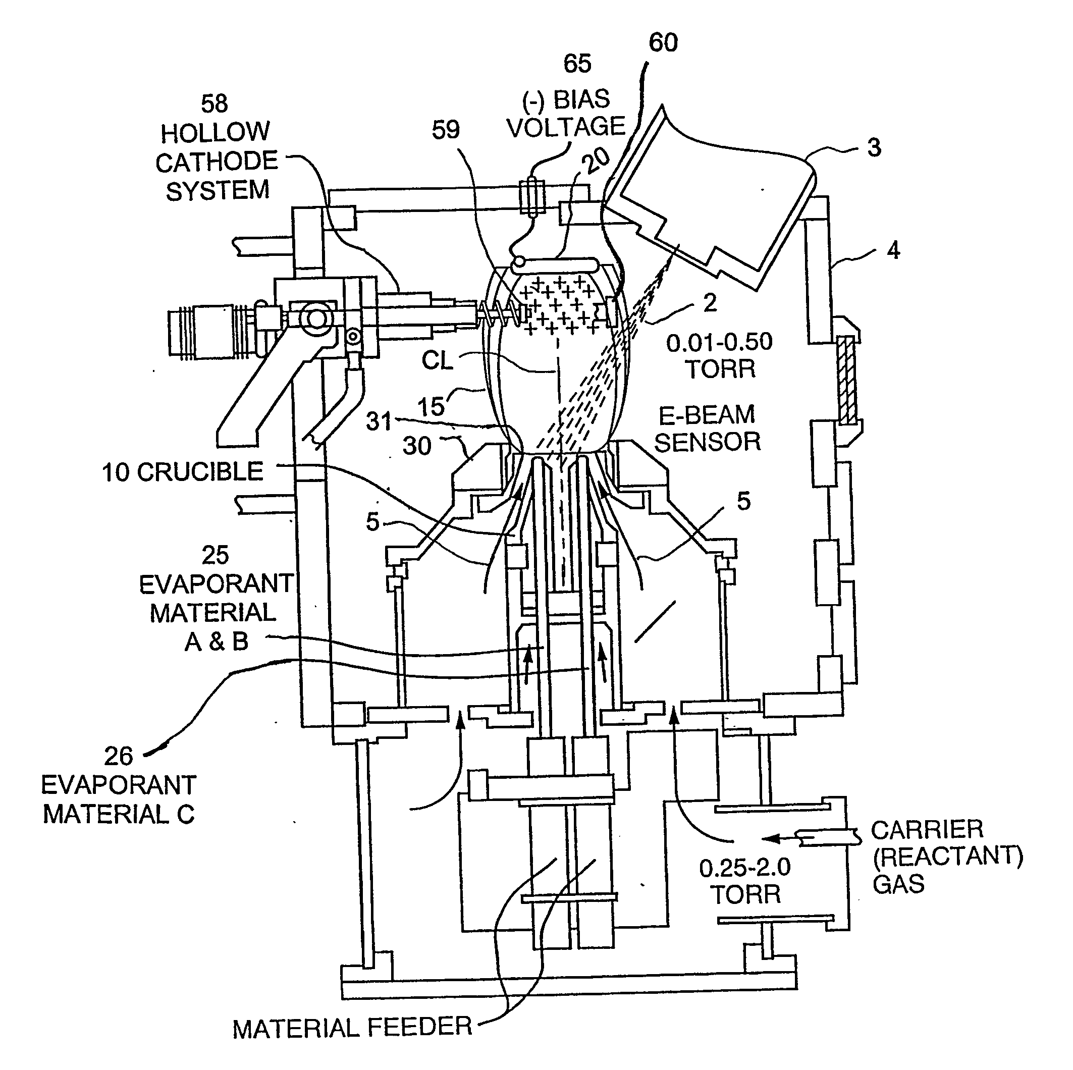
[0030] The present invention provides a method and an apparatus for efficiently applying a dispersion strengthened bond coating to a surface for thermal barrier coating systems using a directed vapor deposition (DVD) approach. To overcome the limitations incurred by conventional methods, the present invention uses a modified energetic beam directed vapor deposition (DVD) technique to evaporate and deposit compositionally and morphologically controlled bond coats at high rate. In one modality, the present invention DVD technique uses the combination of an energetic beam source (e.g., beam gun) (capable of processing material in a low vacuum environment) and a combined inert gas / reactive gas carrier jet of controlled composition to create engineering films. In this system, the vaporized material can be entrained in the carrier gas jet and deposited onto the substrate at a high rate and with a high materials utilization efficiency. The velocity and flux of the gas atoms entering the chamber, the nozzle parameters, and the operating chamber pressure can all be significantly varied, facilitating wide processing condition variation and allowing for improved control over the properties of the deposited layer. In particular, under some (higher pressure / evaporation rate) processing conditions, nanoscopic particles can be reactively formed in the vapor and incorporated in the cooling.
[0031] In another aspect of the present invention, by employing plasma enhancement, multisource crucibles and appropriate process condition control, the morphology, composition, dispersoid size and concentration, the bondcoat grain size and porosity of deposited layers are all controlled. In a second modality, the present invention uses a different evaporation source to reactively create dispersoids which are then entrained in the vapor plume used for depositing the coating. In a third modality, dispersoids are created before deposition and are entrained in the noble gas stream and used to transport the bond coat vapor to the component surface. In modalities one, two, and three a plasma may also be used to control the bond coat structure. In all modalities, the result is a low cost deposition approach for applying bond coats which can have compositions and dispersoids distributions which are difficult to deposit using other conventional approaches.
[0038] In a fourth embodiment, the present invention provides component having a thermal barrier coating system on a substrate thereof, the thermal barrier coating system includes a bond coat deposited on at least a portion of the substrate by a directed vapor deposition (DVD) technique, wherein said bond coat comprises dispersoids in said bond coat; and a thermal-insulating layer overlying at least a portion of the bond coat. The component may be produced by the present invention methods discussed throughout this document. The advantages of the present invention include, but are not limited to: improved use of expensive gases, increased deposition efficiency, and improved uniformity in the coating,
[0039] The result is a dramatically improved method for the efficient application of a bond coating to a surface for thermal barrier systems wherein the bond coat(s) has an improved life expectancy and performance due to the mitigation of yield and creep effects.

Problems solved by technology

In all modalities, the result is a low cost deposition approach for applying bond coats which can have compositions and dispersoids distributions which are difficult to deposit using other conventional approaches.

Method used


Image

  • Method and apparatus for dispersion strengthened bond coats for thermal barrier coatings
  • Method and apparatus for dispersion strengthened bond coats for thermal barrier coatings
  • Method and apparatus for dispersion strengthened bond coats for thermal barrier coatings

Examples


Embodiment Construction

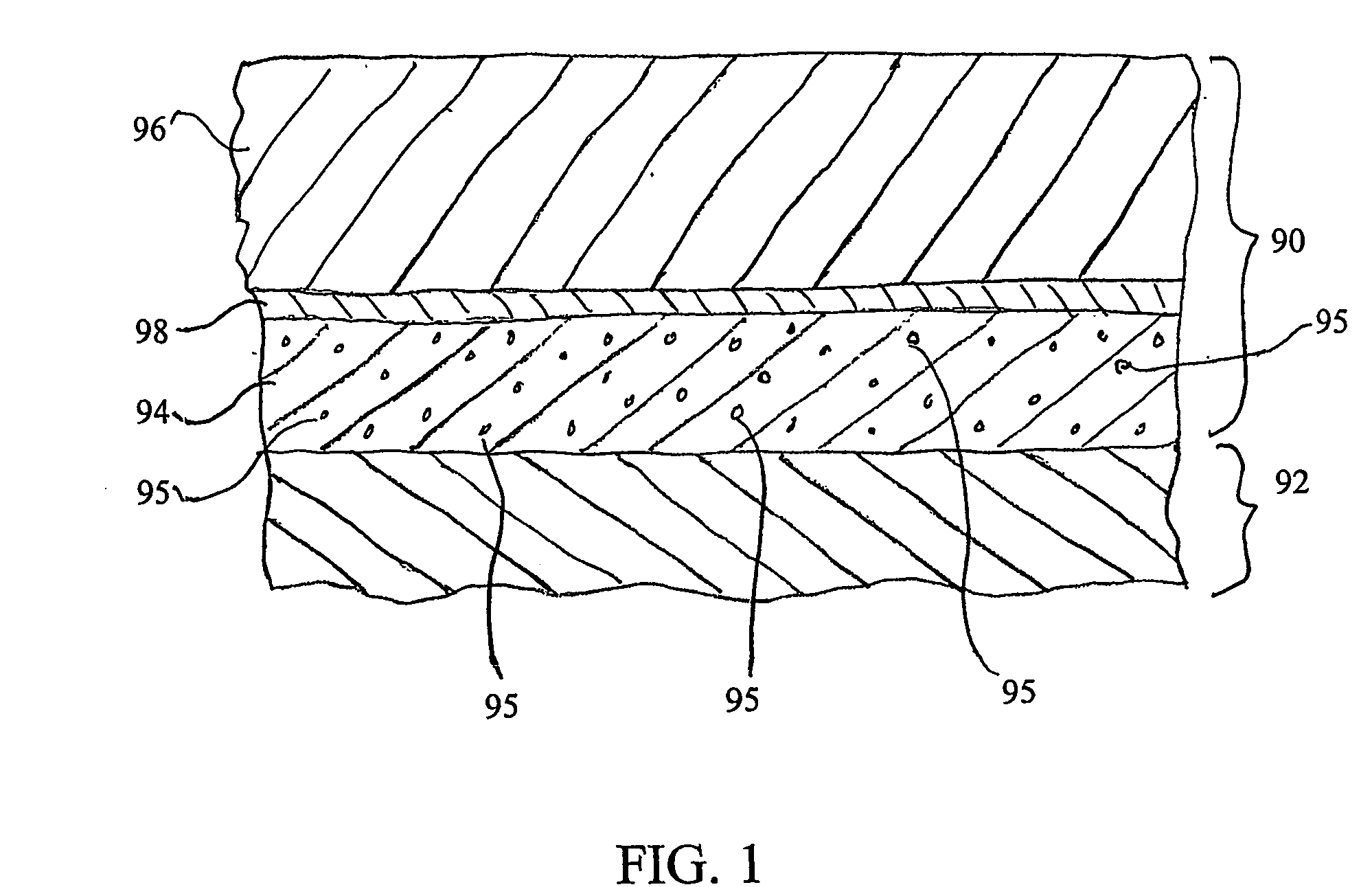
[0052] The present invention is an improved thermal barrier coating (and related method and system for making) which comprises, among other things, a) a substrate typically a nickel base superalloy, b) a dispersion strengthened bond coat and c) a ceramic insulating layer or layers on top. The dispersion strengthened bond coat in this invention is novel in that, but not limited thereto, it produces improved coating system life due to greater yield and creep strength. It may also improve the adhesion of the TGO layer to the bondcoat and enable top coats of preferred morphology to be nucleated. The bond coat consists of one or more metallic or intermetallic phases with a dispersoid of about 1-100 nanometer diameter particles throughout. The volume fraction of the dispersoid is at least about 0.5% but can be varied from about 10%. The preferred compositions for the metallic or intermetallic portion are 1) Ni—50 atom % Al, 2) 50 atom% Ni+Pt—50 atom % Al. Additions of Cr, and oxygen activ...


PUM

PropertyMeasurementUnit
Pressureaaaaaaaaaa
Temperatureaaaaaaaaaa
Pressureaaaaaaaaaa

Abstract

A directed vapor deposition (DVD) method and system for applying at least one bond coating on at least one substrate for thermal barrier coating systems. The method and system provides for alloy strengthening in high temperature metallic alloys that can be melt or solid state processed to materials that one applies by vapor deposition. The creep strengthened coating contains nanoscopic particles of oxides, nitrides, borides, carbides, and other materials which are formed by reactive codeposition. An approach for reactive codeposition is plasma assisted directed vapor deposition. Accordingly, the resultant structure may be utilized for, but not limited thereto, high temperature coatings, e.g. for protecting rocket or power turbines, or diesel engine components. The resultant structure is has a greatly extended lifetime attributed in part to the elimination of coating spallation by the “rumpling” mechanism.

Description

RELATED APPLICATIONS [0001] The present invention claims priority from U.S. Provisional Application Ser. No. 60 / 398,384 filed Jul. 25, 2002, entitled “dispersion Strengthened Bond Coats for Thermal Barrier Coatings and related Method and System thereof” the entire disclosure of which is hereby incorporated by reference herein. [0002] The present application is also related to International Application No. PCT / US02 / 28654, filed Sep. 10, 2002 entitled “Method and Apparatus for Application of Metallic Alloy Coatings,” of which is assigned to the present assignee and is hereby incorporated by reference herein in its entirety.GOVERNMENT SUPPORT [0003] This invention was made with government support under the Office of Naval Research -N00014-00-1-0438. The government has certain rights in the invention.FIELD OF THE INVENTION [0004] The present invention provides a method and an apparatus for efficiently applying a bond coat to a surface for thermal barrier coating systems using a directed...

Claims


Application Information

Patent Timeline
IPC IPC(8): C23C14/06C23C14/30C23C14/32C23C14/54C23C16/00C23C28/00
CPCC23C14/0688C23C14/228C23C14/30C23C14/32C23C14/548H01J2237/3137C23C28/345C23C28/3455F05B2230/90F05C2253/12C23C28/324
Inventor WADLEY, HAYDN N. G.WORTMAN, DAVID J.
Owner UNIV OF VIRGINIA ALUMNI PATENTS FOUND
Learn More