
Micro crystal fiber lasers and method of making frequency-doubling crystal fibers

Active Publication Date: 2006-01-05
IND TECH RES INST
View PDF7 Cites 6 Cited by
  • Summary
  • Abstract
  • Description
  • Claims
  • Application Information

AI Technical Summary

Benefits of technology

[0006] In view of the foregoing, an objective of the invention is to provide a micro crystal fiber laser and a method of making a frequency-doubling crystal fiber. The micro crystal fiber laser includes gain crystal fibers, frequency-doubling crystal fibers, and a semiconductor laser, using crystal fibers to replace the gain medium and frequency-doubling crystal to save the solid state laser crystal. The high specific surface area of the crystal fiber also avoids the heat dissipation problem.
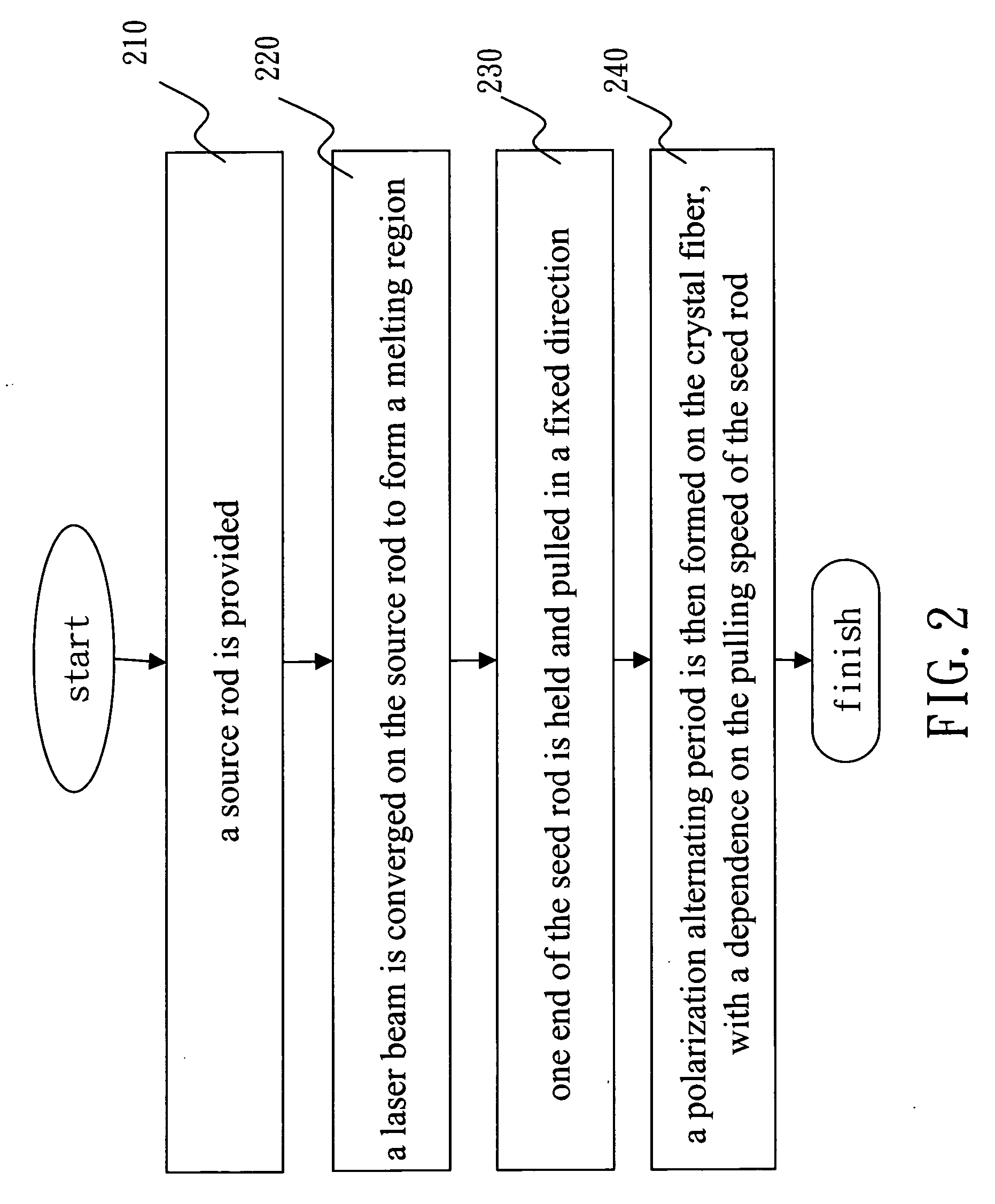
[0008] The invention further discloses a method of making the frequency-doubling crystal fiber with a polarization alternating period. There are many methods of growing crystal fibers. In particular, not only can the laser-heated pedestal growth (LHPG) method readily grow single crystals with extremely small diameters, it has a fast growth speed, low power consumption, and easy control without any pollution problem. The disclosed method employs the LHPG method to form a crystal fiber. The steps include: providing a source rod as the ingredient of the crystal fiber; converging a laser beam on the source rod to form a melting region; holding one end of the seed rod and pulling it toward one fixed direction in order to form a thin crystal fiber from the melting region of the source rod; and providing a pair of electrodes on both sides of the crystal fiber. The electrodes continuously alternate their polarizations according to an external electric field. According to the pulling speed of the seed rod, a polarization alternating period is produced to form a polarization alternating period on the crystal fiber. Moreover, an appropriate material can be used to cover the fiber for reducing the transmission consumption. The required crystal fiber is formed by further lapping, polishing, and coating.
[0009] The cross section of the solid state laser crystal used in the conventional DPSSL is about 10 mm2. In practice, the excited area of the solid laser crystal is only hundreds of squared micrometers (μm2). The invention makes a crystal fiber several hundred micrometers in diameter. The material used in the solid state laser crystal can be greatly reduced. At the same time, the heat conduction path inside the disclosed crystal fiber is much shorter than that inside the conventional laser crystal. The heat dissipation efficiency of the invention is thus better.

Problems solved by technology

Semiconductor lasers in the blue and green bands are restricted by the problems of high prices, difficult production processes, and low light emission rate of wide energy gap semiconductor materials.
Therefore, their commercialization still requires further researches and improvement.
In the horizontal excitation modes, the heat dissipation problem is especially serious, affecting the laser output efficiency.
To solve this problem, a large heat dissipation system is often required.
Moreover, the growth of the solid state laser crystal is very time-consuming, inevitably increasing the device price.
Consequently, the current development of DPSSL is seriously restricted by the cost and heat dissipation.

Method used


Image

  • Micro crystal fiber lasers and method of making frequency-doubling crystal fibers
  • Micro crystal fiber lasers and method of making frequency-doubling crystal fibers
  • Micro crystal fiber lasers and method of making frequency-doubling crystal fibers

Examples


Embodiment Construction

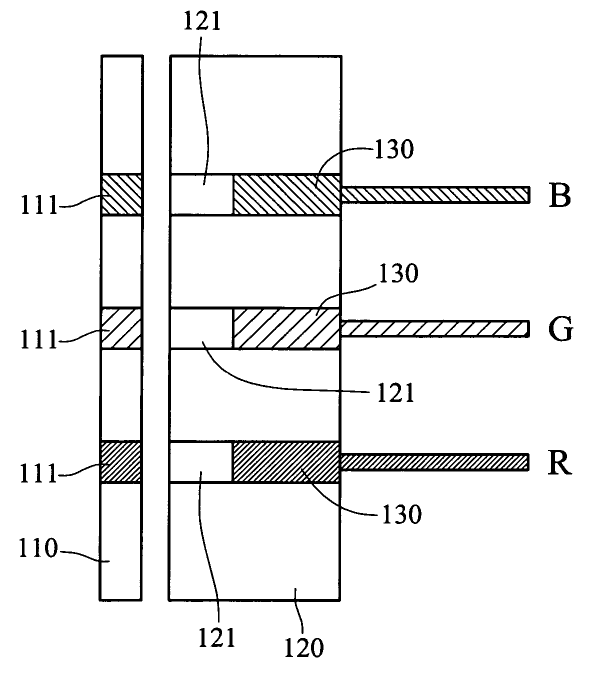
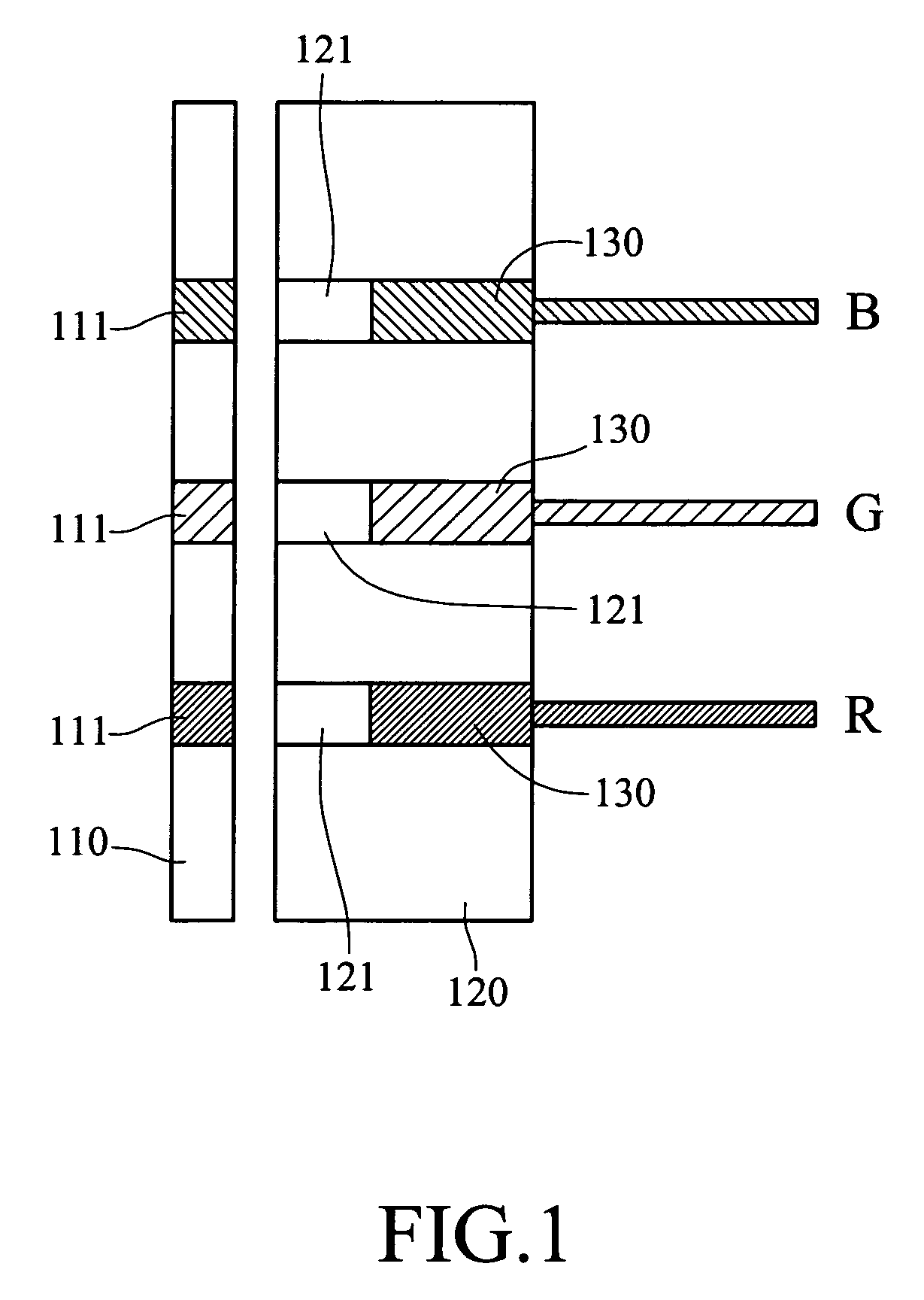
[0013] The disclosed micro crystal fiber laser can be used to make lasers in red, green, and blue colors. The lasers of different colors can be combined into an array to provide a full-color laser. As shown in FIG. 1, the micro crystal fiber laser array according to an embodiment of the invention includes a semiconductor laser array 110, three gain crystal fibers 121, and three frequency-doubling crystal fibers 130. The semiconductor laser array 110 consists of three semiconductor lasers 111 to provide stimulated light. The gain crystal fibers 121 are aligned with and coupled to the frequency-doubling crystal fibers 130 and are installed on a fixing base 120. Each of the gain crystal fibers 121 is used to receive the stimulated light and generate base-frequency light. Each of the frequency-doubling crystal fibers 130 has a polarization alternating period. The frequency-doubling crystal fibers 130 are respectively coupled to the gain crystal fibers 121. Different polarization alterna...


PUM


Abstract

A method of fabricating micro crystal fiber lasers and frequency-doubling crystal fibers is disclosed. The micro crystal fiber laser contains gain crystal fibers, frequency-doubling crystal fibers, and a semiconductor laser. The semiconductor laser provides a laser beam. The gain crystal fibers receive the laser beam and generate a base-frequency beam. The frequency-doubling crystal fibers have a polarization alternating period. The frequency-doubling crystal fibers are coupled to the gain crystal fibers to double the frequency of the base-frequency beam and provide a double-frequency beam with the required wavelength. In addition to providing a monochromic crystal fiber laser, the crystal fiber lasers in red, green, and blue light may be combined into an array, providing a color laser. The frequency-doubling crystal fiber can be formed using the LHPG method. During the production process, a polarization alternating external field is continuously imposed on the frequency-doubling crystal fiber, resulting in a polarization alternating period.

Description

BACKGROUND OF THE INVENTION [0001] 1. Field of Invention [0002] The invention relates to a micro crystal fiber laser and, in particular, to a micro crystal fiber laser for color lasers, a micro crystal fiber laser array, and a method of fabricating a frequency-doubling crystal fiber. [0003] 2. Related Art [0004] Laser beams are characteristic in their high power density, highly monochromic color, high orientability, and high correlation. Therefore, they are widely used in various fields such as medical therapy, communications, information technology, and industries. Among the laser devices for generating laser beams, semiconductor lasers have the advantages of small volumes, long life cycles, cheap prices, and being suitable for mass production, in comparison with other types of laser devices (e.g. gas lasers and solid state lasers). Thus, they can be commercialized. However, in the three primitive colors (red, green, and blue) of visible light, only red semiconductor lasers can be ...

Claims


Application Information

Patent Timeline
IPC IPC(8): H01S3/30H01S3/10H01S3/00H01S3/06H01S3/0941H01S3/109H01S3/16H01S3/23H01S5/02
CPCH01S3/0604H01S3/0627H01S3/09415H01S3/109H01S3/2391H01S3/1643H01S3/1673H01S3/2383H01S3/1611
Inventor HUANG, SHENG-LUNGLO, CHIA-YAOHUANG, SHENG-PANYIN, SUN-BIN
Owner IND TECH RES INST
Learn More