System and methods for performing endovascular procedures

Inactive Publication Date: 2006-03-16
EDWARDS LIFESCIENCES LLC
View PDF2 Cites 238 Cited by
  • Summary
  • Abstract
  • Description
  • Claims
  • Application Information

AI Technical Summary

Benefits of technology

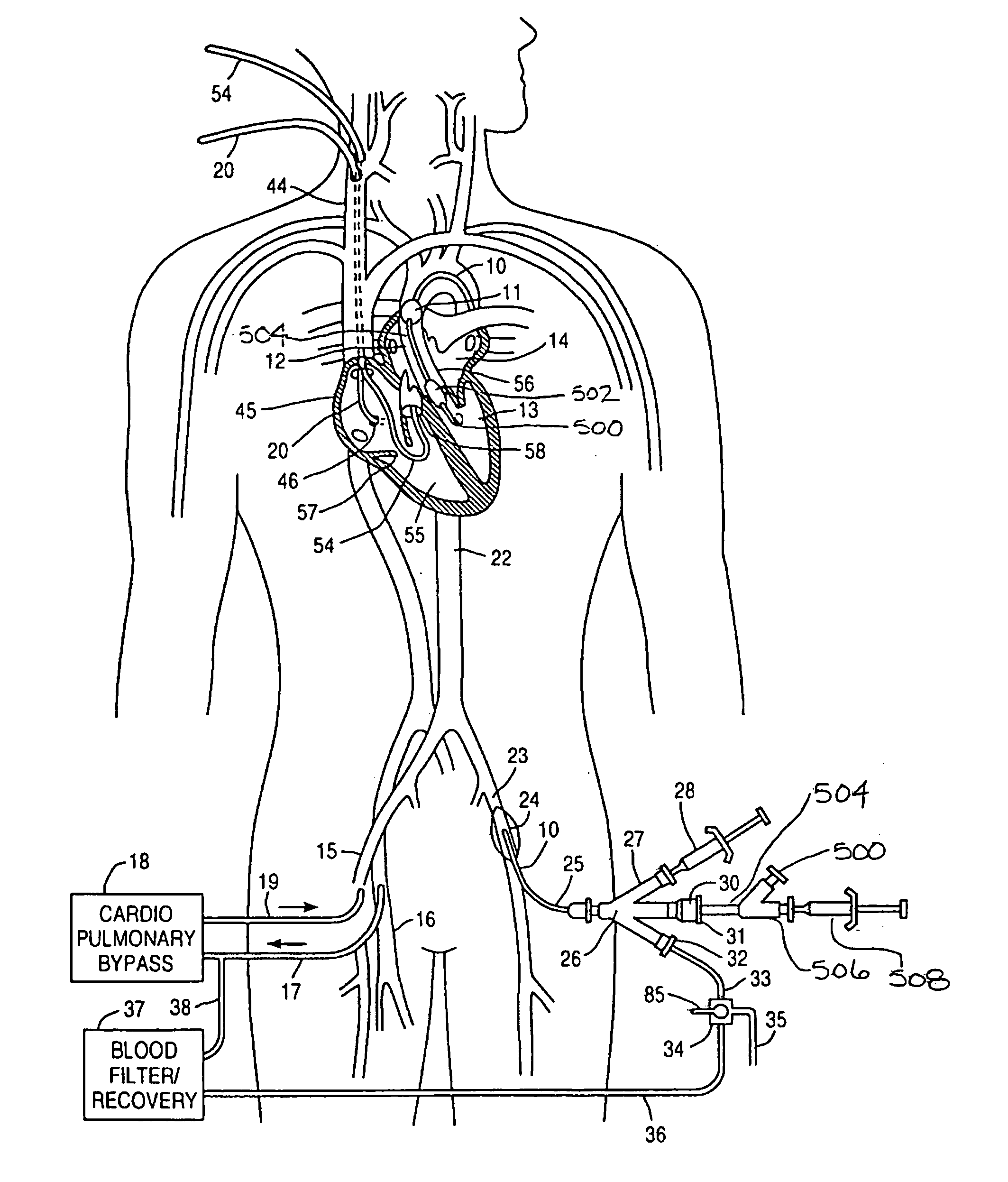
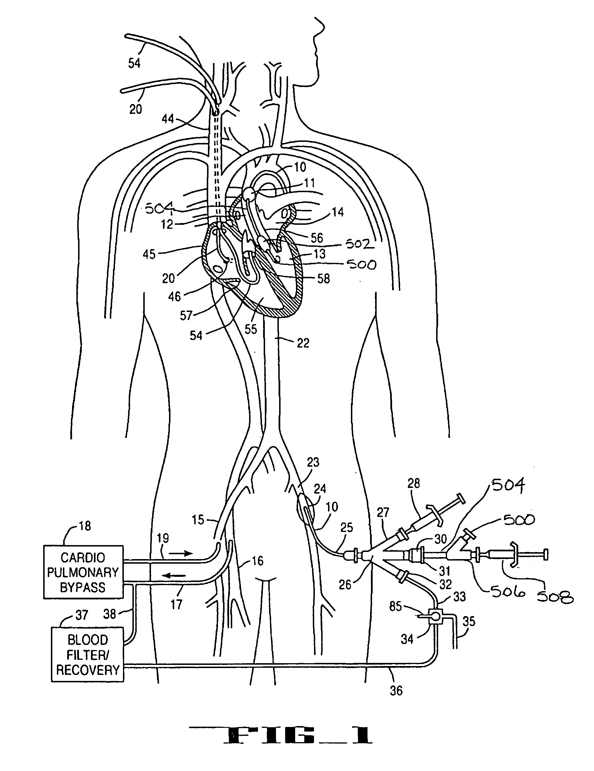
[0013] A number of important advantages accrue from the combination of the endoaortic partitioning catheter with these endovascular diagnostic and therapeutic devices. Introducing endovascular devices through a lumen of the endoaortic partitioning catheter allows the patient's heart to be stopped and the circulatory system supported on cardiopulmonary bypass while performing the endovascular procedure. This may allow the application of various endovascular procedures to patients whose cardiac function is highly compromised and therefore might not otherwise be good candidates for the procedure. It also allows the endovascular procedures to be performed as an adjunct to other cardiac surgical procedures. With the devices of the prior art, it would be difficult to perform many of these endovascular procedures as an adjunct to cardiac surgery because the standard aortic crossclamps used entirely occlude the lumen of the aorta preventing the endovascular devices from being introduced through the normal transluminal route. Many of the diagnostic or therapeutic endovascular procedures will also benefit from performing the procedures while the heart is still and with no blood flow through the heart that would complicate the procedures. For instance ablation of anomalous structures such as calcifica

Problems solved by technology

To date there has only been very limited cli

Method used


Image

  • System and methods for performing endovascular procedures
  • System and methods for performing endovascular procedures
  • System and methods for performing endovascular procedures

Examples


third embodiment

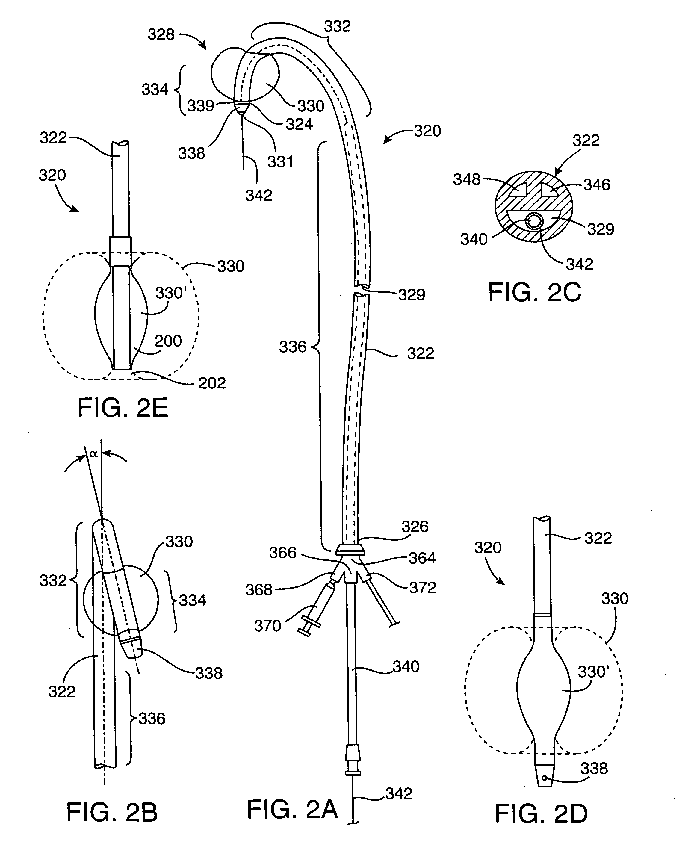
[0055] In a third embodiment, shown in FIGS. 4A-4B, partitioning device 320 includes a shaping element 440 positionable in a lumen in shaft 322, such as third inner lumen 348. Shaping element 440 has a proximal end 442, a distal end 444 and a preshaped distal portion 446. Preshaped distal portion 446 may be generally U-shaped as illustrated, or may have an angular, “S”-shaped or other configuration in an unstressed condition, which will shape distal portion 332 to generally conform to at least a portion of the patient's aortic arch. Shaping element 440 is preferably stainless steel, nickel titanium alloy, or other biocompatible material with a bending stiffness greater than that of shaft 322 so as to deflect distal portion 332 into the desired shape. Shaping element 440 may be a guidewire over which shaft 322 is advanced to the ascending aorta, or a stylet which is inserted into third inner lumen 348 after shaft 322 is positioned with balloon 330 in the ascending aorta. In a preferr...

first embodiment

[0079]FIG. 12B shows an intravascular ultrasonic imaging catheter 584 suitable for use with the present system for performing endovascular procedures. The intravascular ultrasonic imaging catheter 584 has a piezoelectric transducer 586 which is mounted in the distal end of the catheter shaft 594 facing proximally. The piezoelectric transducer 586 is activated to produce pulses of ultrasonic energy. An angled reflective, rotating, ultrasonic mirror 588 directs the ultrasonic pulses from the piezoelectric transducer 586 radially outward from the catheter 584 to create an ultrasonic beam that sweeps in a 360° path around the catheter. The ultrasonic pulses are reflected off of structures in the tissue surrounding the ultrasonic imaging catheter 584. The reflected echoes strike the rotating mirror 588 and are directed back toward the piezoelectric transducer 586 which converts the received ultrasonic reflections to electrical signals. The electrical signals from the piezoelectric transd...

second embodiment

[0080]FIG. 12C shows an intravascular ultrasonic imaging catheter 596 suitable for use with the present system for performing endovascular procedures. The intravascular ultrasonic imaging catheter 596 has a focused piezoelectric transducer 598 which is mounted on the distal end of a flexible drive shaft 600 facing radially outward. The piezoelectric transducer 598 and the flexible drive shaft 600 are surrounded by a protective sonolucent sheath 602. The piezoelectric transducer 598 is activated to produce pulses of ultrasonic energy as the flexible drive shaft 600 rotates to create an ultrasonic beam that sweeps in a 360° path around the catheter. The ultrasonic pulses are reflected off of structures in the tissue surrounding the ultrasonic imaging catheter 596. The reflected echoes strike the rotating mirror 588 and are directed back toward the piezoelectric transducer 598 which converts the received ultrasonic reflections to electrical signals. The electrical signals from the piez...


PUM


Abstract

A system for inducing cardioplegic arrest and performing an endovascular procedure within the heart or blood vessels of a patient. An endoaortic partitioning catheter has an inflatable balloon which occludes the ascending aorta when inflated. Cardioplegic fluid may be infused through a lumen of the endoaortic partitioning catheter to stop the heart while the patient's circulatory system is supported on cardiopulmonary bypass. One or more endovascular devices are introduced through an internal lumen of the endoaortic partitioning catheter to perform a diagnostic or therapeutic endovascular procedure within the heart or blood vessels of the patient. Surgical procedures such as coronary artery bypass surgery or heart valve replacement may be performed in conjunction with the endovascular procedure while the heart is stopped. Embodiments of the system are described for performing: fiberoptic angioscopy of structures within the heart and its blood vessels, valvuloplasty for correction of valvular stenosis in the aortic or mitral valve of the heart, angioplasty for therapeutic dilatation of coronary artery stenoses, coronary stenting for dilatation and stenting of coronary artery stenoses, atherectomy or endarterectomy for removal of atheromatous material from within coronary artery stenoses, intravascular ultrasonic imaging for observation of structures and diagnosis of disease conditions within the heart and its associated blood vessels, fiberoptic laser angioplasty for removal of atheromatous material from within coronary artery stenoses, transmyocardial revascularization using a side-firing fiberoptic laser catheter from within the chambers of the heart, and electrophysiological mapping and ablation for diagnosing and treating electrophysiological conditions of the heart.

Description

CROSS-REFERENCE TO RELATED APPLICATIONS [0001] This application is a continuation-in-part of application of copending U.S. patent application Ser. No. 08 / 282,192, filed Jul. 28, 1994, which is a continuation-in-part of application Ser. No. 08 / 162,742, filed Dec. 3, 1993, which is a continuation-in-part of application Ser. No. 08 / 123,411, filed Sep. 17, 1993, which is a continuation-in-part of application Ser. No. 07 / 991,188, filed Dec. 15, 1992, which is a continuation-in-part of application Ser. No. 07 / 730,559, filed Jul. 16, 1991, which issued as U.S. Pat. No. 5,370,685 on Dec. 6, 1994. This application is also a continuation-in-part of copending U.S. patent application Ser. No. 08 / 159,815, filed Nov. 30, 1993, which is a U.S. counterpart of Australian Patent Application No. PL 6170, filed Dec. 3, 1992. This application is also a continuation-in-part of copending U.S. patent application Ser. No. 08 / 281,962, filed Jul. 28, 1994, which is a continuation-in-part of application Ser. N...

Claims


Application Information

Patent Timeline
IPC IPC(8): A61M31/00
CPCA61B17/320783A61B17/3421A61B2017/00243A61B2017/22067A61M2025/1052A61F2/958A61M25/0032A61M25/10A61M2025/0681A61B2019/528A61B2090/3784
Inventor STEVENS, JOHN H.PETERS, WILLIAM S.STERMAN, WESLEY D.GIFFORD, HANSON S. III
Owner EDWARDS LIFESCIENCES LLC
Why Eureka
Try Eureka