
Nano-structured ion-conducting inorganic membranes for fuel cell applications

Inactive Publication Date: 2006-04-13
YANG LAIXIA +2
View PDF7 Cites 140 Cited by
  • Summary
  • Abstract
  • Description
  • Claims
  • Application Information

AI Technical Summary

Benefits of technology

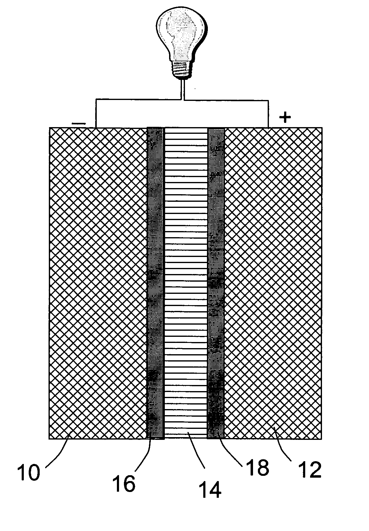
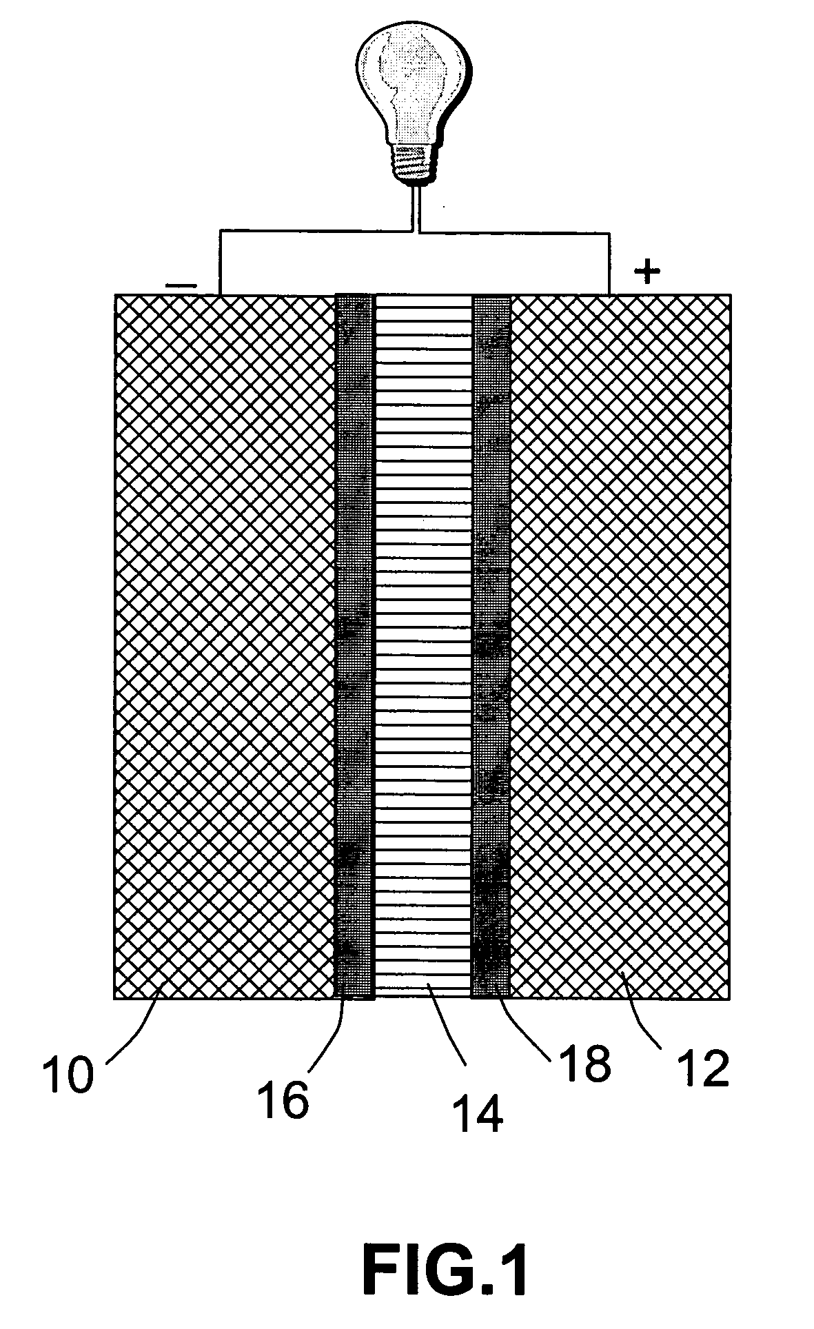
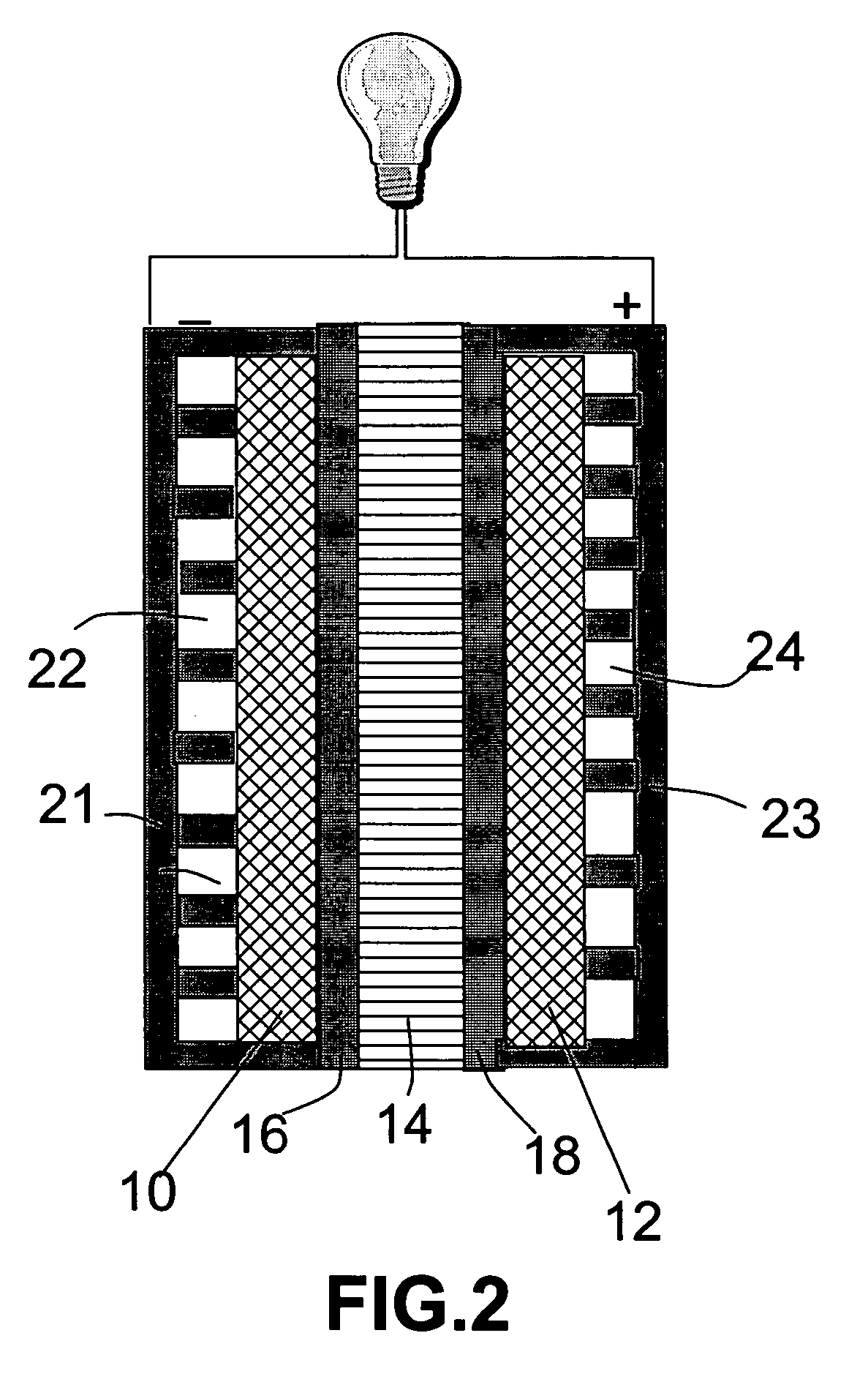
[0016] The present invention provides an inorganic proton conducting membrane and a fuel cell containing such a membrane. The fuel cell is mainly composed of a fuel anode, an oxidant cathode, and a proton-conducting membrane disposed between the anode and the cathode. The membrane is unique in that it is based on an inorganic material such as an oxide-based super-acid that can be used at a relatively high temperature (e.g. 150° C. or higher) that is otherwise not possible with a PSFA-type of polymer membrane. The membrane comprises a nano-structured network of proton-exchange inorganic particles, characterized in that the particles form a sufficiently high density of proton-conducting nanometer-scaled channels (with at least one dimension smaller than 100 nanometers) so that ionic conductivity of the membrane is no less than 10−6 S / cm (mostly greater than 10−4 S / cm ) at 25° C. or no less than 10−4 S / cm (mostly greater than 10−2 S / cm) at 200° C. Such a high temperature allows a hydrogen-oxygen fuel cell to operates very efficiently without the need (or with a reduced need) to maintain the membrane in a highly hydrated state. A fast electro-catalytic reaction of a fuel (e.g., mixture of methanol and water) at the anode due to a higher operating temperature also implies a lesser amount of fuel available for crossover and a higher fuel utilization efficiency.

Problems solved by technology

Currently, these materials, when used as a fuel cell membrane, suffer from three serious technical problems:
One problem is that this type of polymer membrane requires the presence of water for ion conductivity.
This dependence on water is a drawback of membranes that rely on sulfonic acid groups for their conductivity.
In each case, it requires additional water-handling components and raises the system complexity and cost.
The second problem is particularly severe for the direct organic liquid fuel cell (e.g., DMFC and DEFC).
This is associated with low fuel utilization efficiency due to methanol or ethanol crossover from the anode through the electrolyte membrane to reach the cathode without being utilized.
Using DMFC as an example, methanol crossover substantially degrades the performance of DMFCs.
The methanol that crosses over represents lost fuel value and, therefore, a lower fuel efficiency.
None of the energy from this oxidation is used to produce electrons and, hence, it all ends up as waste heat, increasing the cooling load on the cell.
Additionally, as a third problem, a fuel cell containing a PFSA-type PEM has exhibited poor performance due to low electrode reactivity.
Unfortunately, PFSA-type membrane materials cannot be used at high temperatures (e.g., higher than 100° C.) for an extended period of time without degradation.
The inability to produce thin sheets has been a key weakness of materials produced by the method used by Nakamora et al.
Although the approach proposed by Murphy, et al. represents a significant improvement over conventional PFSA PEM or other polymer-filler composite approaches, it still has the following drawbacks: (1) Since the polymer is the continuous matrix with the inorganic particles dispersed therein, there is only limited volume of channels through which ions can transport.
In addition, those isolated particles (not a part of a chain) would not significantly contribute to ion conductivity.
(2) The polymer represents the majority phase of the composite structure and, hence, the end-use temperature of such a composite membrane is limited by the thermal stability of the polymer.
Although the ionic conductivity of this composite can be very high, its high-temperature durability is questionable.

Method used


Image

  • Nano-structured ion-conducting inorganic membranes for fuel cell applications
  • Nano-structured ion-conducting inorganic membranes for fuel cell applications
  • Nano-structured ion-conducting inorganic membranes for fuel cell applications

Examples


example 1

[0042] A fuel cell was prepared as follows. A sheet of carbon paper was coated on one side with a Pt—Ru catalyst to give an anode of 32 mm×32 mm in dimensions. A carbon paper was coated with a platinum (Pt) black catalyst to give a cathode also of 32 mm×32 mm. The Pt-coated carbon paper was then placed in a sputtering chamber to serve as a substrate. A piece of H3[P.Mo.O40].30H2O crystal was used as a sputtering target. A thin film with a thickness of approximately 0.5 μm was deposited onto the substrate for use as a thin solid electrolyte layer. This inorganic electrolyte membrane was then pressed against the catalyst side of the anode layer in such a way that the membrane is sandwiched between the anode and the cathode, with the catalyst layers on both electrodes being in contact with the electrolyte membrane. The assembly was joined together by pressing for 5 minutes under a pressure of 20 kg / cm2, to give a power generating section. The resulting assembly was held between a catho...


PUM


Abstract

An inorganic proton-conducting membrane and a fuel cell comprising this membrane. The fuel cell comprises a fuel anode, an oxidant cathode, and an inorganic proton-conducting membrane disposed between the anode and the cathode. The membrane is composed of a nano-structured network of proton-exchange inorganic particles. The particles form a sufficiently high density of proton-conducting nanometer-scaled channels with at least one dimension smaller than 100 nanometers so that ionic conductivity of the membrane is no less than 10−6 S / cm (mostly greater than 10−4 S / cm ) at 25° C. or no less than 10−4 S / cm (mostly greater than 10−2 S / cm) at 200° C. This inorganic membrane allows a hydrogen-oxygen fuel cell to operate at a higher temperature without the need (or with a reduced need) to maintain the membrane in a highly hydrated state. A higher operating temperature also implies a fast electro-catalytic reaction of a fuel (e.g., mixture of methanol and water) at the anode permitting a lesser amount of fuel to cross-over the membrane and, hence, a higher fuel utilization efficiency.

Description

[0001] This invention is a result of a research project sponsored by the U.S. National Science Foundation SBIR-STTR Program. The U.S. government has certain rights on this invention.FIELD OF THE INVENTION [0002] This invention relates to an ion-conducting membrane for fuel cell applications. The invention specifically relates to a nano-structured inorganic membrane that has a high density of proton-conducting nano-scaled channels for use in hydrogen-oxygen fuel cells, direct methanol fuel cell (DMFC), direct ethanol fuel cell (DEFC), and the like. BACKGROUND OF THE INVENTION [0003] A fuel cell is a device which converts the chemical energy into electricity. A fuel cell differs from a battery in that the fuel and oxidant of a fuel cell are supplied from sources that are external to the cell, which can generate power as long as the fuel and oxidant are supplied. A particularly useful fuel cell for powering portable electronic devices is a direct methanol fuel cell (DMFC) in which the ...

Claims


Application Information

Patent Timeline
IPC IPC(8): H01M8/00H01M2/14
CPCH01B1/122H01M8/1009H01M8/1016H01M2008/1095H01M2008/1293H01M2300/0071H01M2300/0077H01M2300/0082H01M2300/0091Y02E60/523Y02E60/525Y02E60/50
Inventor YANG, LAIXIAGUO, JIUSHENGJANG, BOR Z.
Owner YANG LAIXIA
Learn More