
Electronic Anti-coagulation stent for intra-arterial deployment

a technology of anticoagulation stent and electrode, which is applied in the field of electrode, can solve the problems of unacceptably short time, complex application of current, and never delivered current to a deployed stent, and achieve the effect of allowing adequate maneuverability of the css

Inactive Publication Date: 2006-05-18
BUSIASHVILI YURI
View PDF16 Cites 55 Cited by
  • Summary
  • Abstract
  • Description
  • Claims
  • Application Information

AI Technical Summary

Benefits of technology

[0015] In order to prevent re-growth of the clot, either spontaneous or iatrogenic, the CSS should be capable of maintaining a negative charge over an extended period of time. The reason for maintaining the negative charge is to prevent regrowth of a clot in the target artery.
[0019] The insulating material is “sandwiched” or positioned between the two concentric metal stents, one inside another, like coaxial cylinders. The electret or other dielectric material functions the same as the dielectric material found in a capacitor. According to my invention, the coaxial stents will play the role of capacitor plates. Construction of the CSS should be simple, allowing easy trackability.
[0022] Electronic anticoagulation is achieved if the inner surface of the inner deployed coaxial stent has a negative static electric charge, as long as it is greater than the charge carried by the platelets. The platelets then will not be attracted to this portion of the deployed stent; clot formation will be prevented.
[0027] Before the coaxial stents are actually deployed and connected to the battery, there is no current flow through the circuit. The coaxial stents are designed so that current can only flow upon deflation of the delivery balloon and deployment of the stent. As each stent is expanded, the contact points between each stent and a respective battery terminal are established. In this manner, the electrical circuit is completed and current flows. A negative charge soon builds up on the inner coaxial stent and a positive charge builds up on the outer coaxial stent. The dielectric material sandwiched between each coaxial stent prevents discharge across each stent.
[0030] Preferably, the inner and outer stent designs will permit the inner stent to have substantially the same inner diameter as the outer stent design upon deployment. Each stent is comprised of expandable rings that are spaced apart from one another and are connected by intermittent linking stems. The spacing of the rings comprising one stent are sufficient to allow the interconnected rings of the other stent construction cylinder to fill the spacing and thereby permit adequate maneuverability of the CSS.

Problems solved by technology

Although application of current to a stent has been tried prior to deployment, current has never been delivered to a deployed stent.
Application of the current is complicated by the fact that blood conducts electric current and any power source such as a battery operably connected to a deployed stent would lose its charge within an unacceptably short time if the sole purpose of the battery was to generate an electric current through a deployed stent.

Method used


Image

  • Electronic Anti-coagulation stent for intra-arterial deployment
  • Electronic Anti-coagulation stent for intra-arterial deployment

Examples


Embodiment Construction

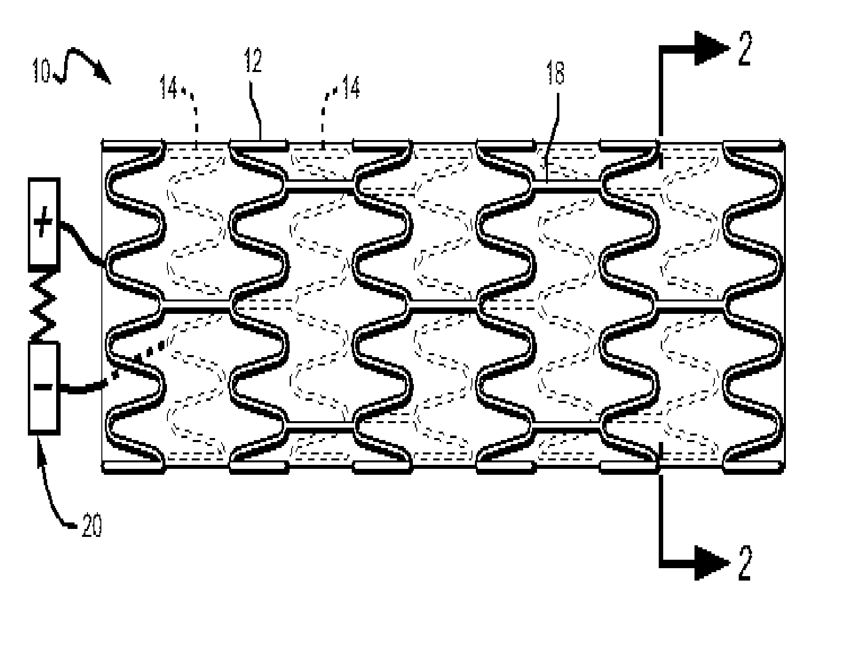
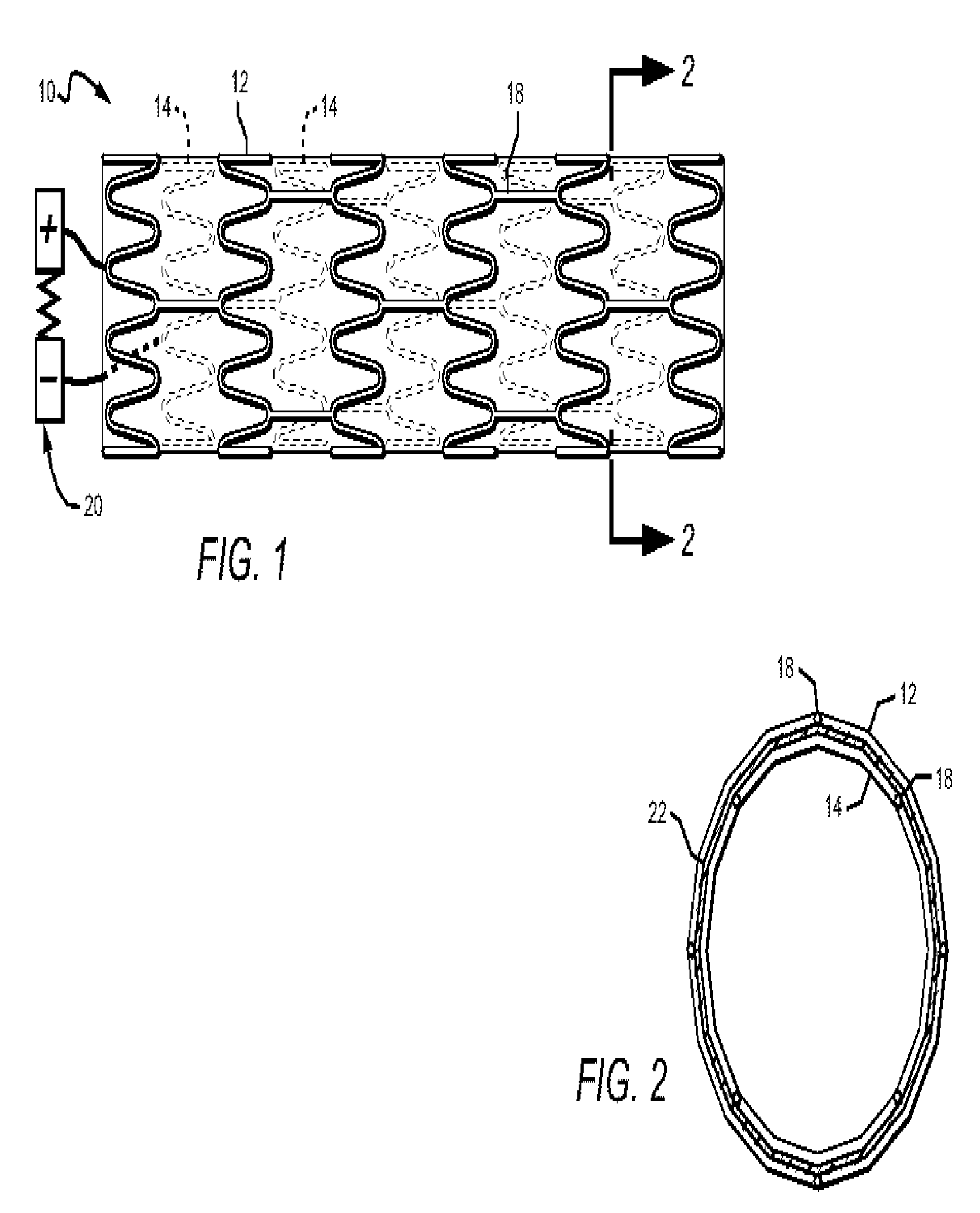
[0034]FIG. 1 provides a schematic side view representation of my coaxial stent structure 10 which comprises an outer stent 12 and an inner stent 14. Stents 12 and 14 are each comprised of a plurality of rings which are sinusoidal in configuration and thus capable of outward expansion. The rings of each stent are connected to adjacent rings by stems 18.

[0035] When the stent structure is deployed, battery 20 becomes operatively connected, its positive terminal connected to outer stent 12 and its negative terminal connected to inner stent 14 upon deployment. It is to be understood that the position of battery 20 illustrated in FIG. 1 is shown to simplify explanation. In the preferred embodiment, battery 20 is preferably physically attached as part of the stent structure near or adjacent the upstream end.

[0036] As best seen in the cross-sectional view of FIG. 2, coaxial stent structure 10 further comprises an insulation layer 22 to prevent conductivity between stents 12 and 14. Insula...


PUM


Abstract

An electronic anti-coagulation stent structure is disclosed. The stent structure comprises a pair of coaxial metal stents having a layer of dielectric material between the stents. A battery is operatively connected preferably near or adjacent to the upstream end upon deployment of the stent. The positive battery terminal establishes an electrical connection to the outer metal stent and the negative terminal establishes an electrical connection to the inner metal stent and this exhibits a capacitor-like properties. The inner metal stent, being negatively charged, promotes a platelet repellent, anti-thrombotic effect.

Description

TECHNICAL FIELD [0001] The invention pertains to the stent specifically designed for prevention of arterial re-stenosis or re-thrombosis, following arterial stenting. BACKGROUND OF THE INVENTION [0002] The anatomical substrate of arterial stenosis is usually either a dissected or injured arterial inner lining, or intima. The damaged intima condition can be affected by natural pathological development such as atherosclerotic plaque, or by invasive intervention, such as balloon angioplasty or stenting. [0003] Critical narrowing of an arterial pathway or its total occlusion can lead to life threatening complications, such as heart attack, arrhythmia, or death. [0004] To prevent such complications, coronary stenting is used to treat critical coronary disease. Re-stenosis occurs in 30-40% of all coronary stenting procedures. Re-stenosis can be successfully reduced in many procedures by the use of drug eluting stents. But even drug eluting stents do not prevent the development of new sten...

Claims


Application Information

Patent Timeline
IPC IPC(8): A61F2/90A61N1/05
CPCA61F2/07A61F2/852A61F2/91A61F2/915A61F2230/0013A61F2002/91541A61F2002/91558A61F2250/0063A61N1/37205A61F2002/075
Inventor BUSIASHVILI, YURI
Owner BUSIASHVILI YURI
Learn More