Electrical heating reactor for gas phase reforming

a technology of electric heating reactor and gas phase, which is applied in the direction of gas-gas reaction process, separation process, products, etc., can solve the problems of investment cost, inability to meet the requirements of large surface area, and many operational problems, and achieves flexible use and high yield.

Inactive Publication Date: 2006-06-15
HYDRO QUEBEC CORP
View PDF34 Cites 74 Cited by
  • Summary
  • Abstract
  • Description
  • Claims
  • Application Information

AI Technical Summary

Benefits of technology

[0068] providing modular reactors, that are co

Problems solved by technology

The formation of free carbon is known to cause many operational problems in reactors, for example with respect to the use of catalytic reactors.
Presently, such membranes are not yet available for applications requiring large surfaces, as this would be required for the production of synthesis gas.
However, the main drawback of such an ap

Method used


Image

  • Electrical heating reactor for gas phase reforming
  • Electrical heating reactor for gas phase reforming
  • Electrical heating reactor for gas phase reforming

Examples


example 1

Lab Reactor Fed with a Mixture of Methane (CH4) and carbon dioxide (CO2) saturated in water vapor (H2O)

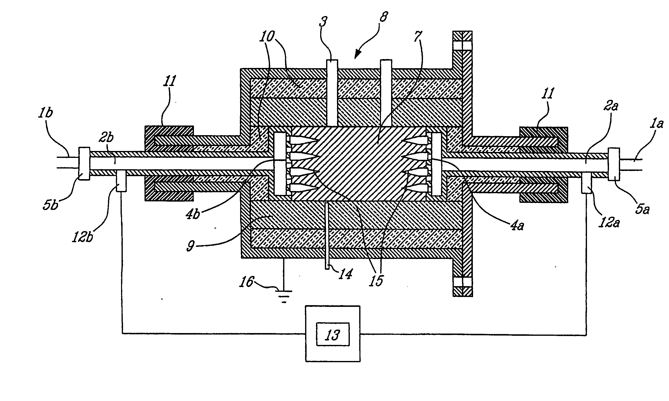
[0298] A compact electrical reactor of small capacity is described generally in FIGS. 2 and 3. According to the assembly of such a reactor, the gaseous reactants, under the circumstances methane (CH4), carbon dioxide (CO2) and water vapor (H2O), are injected into a supply opening consisting of a hollow tube (1a) that is part of a metallic electrode, itself consisting of hollow tube (2a) and a hollow disk (4a). The hollow tubes (1a) and (2a) as well as the hollow disk (4a) are made of soft steel (carbon steel). The inlet electrode (2a and 4a) is electrically insulated with respect to the supply tube (1a) by using a device (5a) made of Teflon®, an electrically insulating material allowing the gases to pass therethrough. The gaseous reactants travel through the openings (6) of the hollow disk (4a) of the electrode and contact the metallic lining (7), which consists of steel wool of ...

example 2

Lab Reactor Fed with a Mixture of Methane (CH4) and Carbon Dioxide (CO2) Saturated with Water Vapor (H2O)

[0359] This second example describes the operation of the lab reactor under operating conditions similar to those indicated in example 1 (reforming test no. 71102). For this example, the time of operation is 340 minutes.

[0360] Table 5 reveals the main parameters measured at times corresponding to the taking of samples.

TABLE 5Main parameters measured when taking samplesof reforming test no. 71102SampleTimeVoltageCurrentResistancePowerTemperature(no.)(min)(V)(A)(Ohm)(W)(° C.)1852.751550.017742679321602.541600.015940677532202.441600.015339076442802.471680.014741576353402.471750.0141432762

[0361] The results presented in Table 6 easily agree, within experimental error, with values based on thermodynamic equilibrium calculations for a same level of temperature.

TABLE 6Results of chemical analyses of the gas mixture producedDuring reforming test no. 71102Normalized concentrations ...


PUM


Abstract

The invention concerns an electrical reactor for reforming, in the presence of an oxidant gas, a gas comprising at least one hydrocarbon, and/or at least one organic compound, including carbon and hydrogen atoms as well as at least one heteroatom. Said reactor comprises: an enclosure, a reaction chamber provided with at least two electrodes comprising at least one conductive lining material electrically isolated from the metal wall of the enclosure, at least one supply of gas to be reformed, at least one oxidant gas supply, at least one outlet for the gases from the reforming and one electrical source for powering the electrodes and resulting in generation of an electronic flux in the conductive lining between the electrodes and in heating said lining.

Description

FIELD OF THE INVENTION [0001] The field of application of this invention resides in the use of electricity for reforming natural gases, organic gases, light hydrocarbons or biogas for example, particularly in view of converting them into synthesis gas, i.e. into mixtures, for example based on carbon monoxide, carbon dioxide and hydrogen which could be used, among others, for the production of basic chemical products such as methanol and dimethylether. The present invention, on the other hand, constitutes a favorable option for the stabilization of greenhouse gas emissions (GES), in the sense that the electrical reforming reactor that is the object of said invention may be supplied for example with carbon dioxide (carbon dioxide consumption). PRIOR ART [0002] It is known since 1834 that it is possible to produce a fuel gas mixture, called synthesis gas, composed of simple molecules of carbon monoxide and hydrogen, by reacting coal with water vapor at elevated temperature. This gas ha...

Claims


Application Information

Patent Timeline
IPC IPC(8): B01J12/00B01J19/08B01D53/32B01J8/02B01J19/24C01B3/34C01B3/38
CPCB01D53/323B01J8/0221B01J8/0285B01J19/088B01J19/2495B01J2208/00415B01J2208/00495B01J2219/00029B01J2219/00033B01J2219/0807B01J2219/0824B01J2219/0845B01J2219/0875B01J2219/0894C01B3/342C01B3/386C01B2203/0222C01B2203/0238C01B2203/06C01B2203/061C01B2203/085C01B2203/0861C01B2203/1011C01B2203/127Y02P20/142
Inventor LABRECQUE, RAYNALDLAFLAMME, CLAUDEBPETITCLERC, MICHEL
Owner HYDRO QUEBEC CORP
Why Eureka
Try Eureka