
Bituminous froth hydrocarbon cyclone

a hydrocarbon cyclone and bitumen technology, applied in the field of bitumen recovery from oil sand, can solve the problems of high maintenance cost, poor bitumen separation, and high capital and operating cost of centrifuge units, and achieve enhanced overflow stream, poor bitumen separation, and enhanced overflow stream

Inactive Publication Date: 2006-06-29
GARNER WILLIAM NICHOLAS +2
View PDF9 Cites 72 Cited by
  • Summary
  • Abstract
  • Description
  • Claims
  • Application Information

AI Technical Summary

Benefits of technology

[0024] In another aspect, the present invention provides a bitumen froth process circuit that uses an arrangement of hydrocarbon cyclones and inclined plate separators to perform removal of solids and water from the bitumen froth that has been diluted with a solvent such as naphtha. The process circuit has an inclined plate separator and hydrocarbon cyclone stages. A circuit configured in accordance with the invention provides a process to separate the bitumen from a hybrid emulsion phase in a bitumen froth. The hybrid emulsion phase includes free water and a water-in-oil emulsion and the circuit of the present invention removes minerals such as silica sand and other clay minerals entrained in the bitumen froth and provides the removed material at a tailings stream provided at a circuit tails outlet. The process of the invention operates without the need for centrifuge equipment. The elimination of centrifuge equipment through use of hydrocarbon cyclone and inclined plate separator equipment configured in accordance with the invention provides a cost saving in comparison to a process that uses centrifuges to effect bitumen de-watering and demineralization. However, the process of the invention can operate with centrifuge equipment to process inclined plate separator underflow streams if so desired.
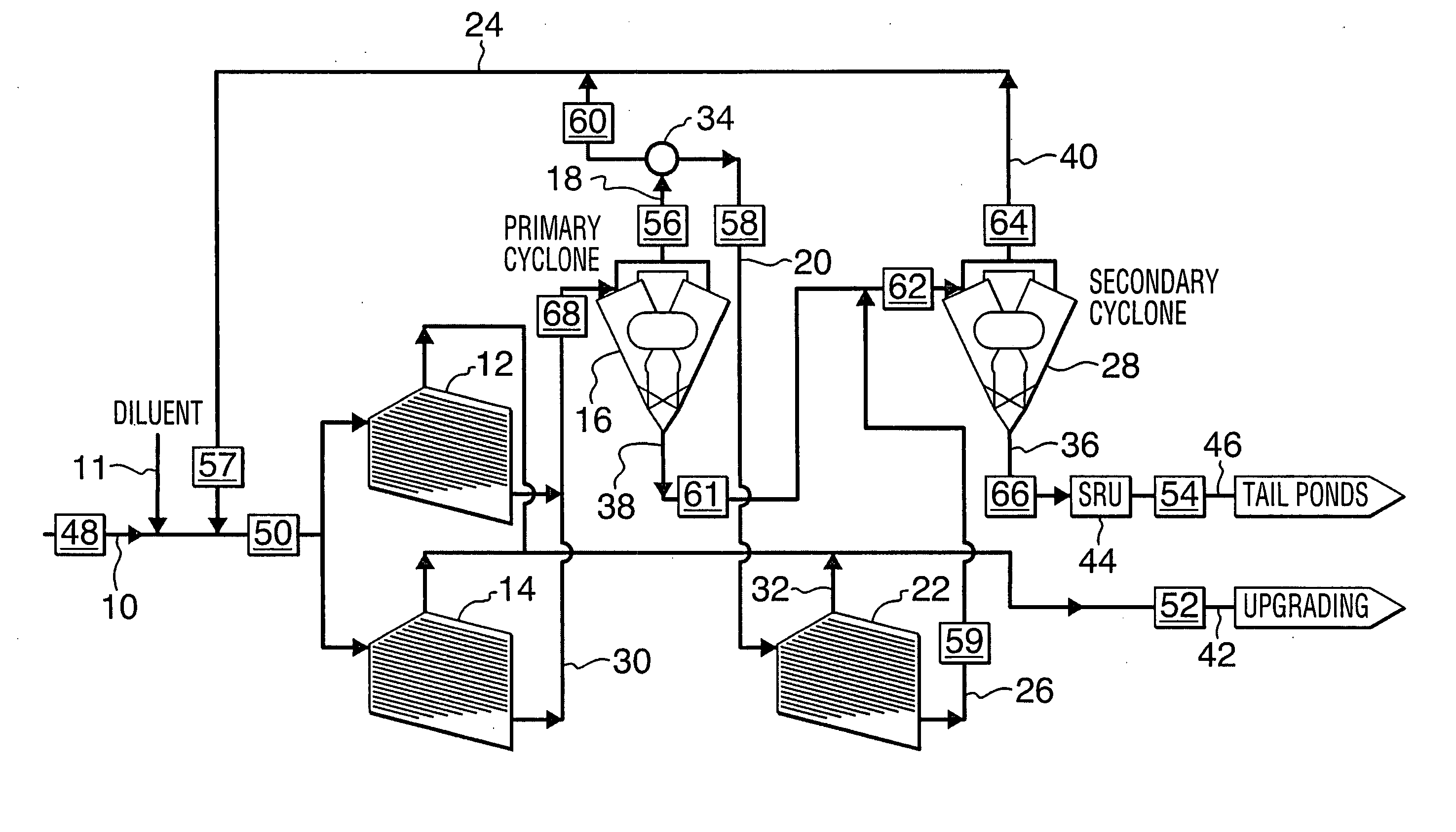
[0026] In accordance with an aspect of the invention, the bitumen froth to be treated is supplied to a circuit inlet for processing into a bitumen product provided at a circuit product outlet and material removed from the processed bitumen froth is provided at a circuit tails outlet. The bitumen froth is supplied to a primary inclined plate separator (IPS) stage, which outputs a bitumen enhanced overflow stream and a bitumen depleted underflow stream. The underflow output stream of the first inclined plate separator stage is a melange containing a variety of various emulsion components supplied as a feed stream to a cyclone stage. The cyclone stage outputs a bitumen enhanced overflow stream and a bitumen depleted underflow stream. The formation of a stubborn emulsion layer can block the downward flow of water and solids resulting in poor bitumen separation. These stubborn emulsion layers are referred to as rag-layers. The process of the present invention is resistant to rag-layer formation within the inclined plate separator stage, which is thought to be a result of the introduction of a recycle feed from the overflow stream of the hydrocarbon cyclone stage.
[0028] The underflow output stream of the first inclined plate separator stage is supplied to a primary hydrocarbon cyclone stage, which transforms this complex mixture into an emulsion that is available from the primary cyclone stage as an overflow output stream. In a preferred arrangement, the overflow output stream of the primary cyclone stage is supplied to an IPS stage to process the emulsion. The overflow output stream of an IPS stage provides a bitumen product that has reduced the non-bitumen components in an effective manner.
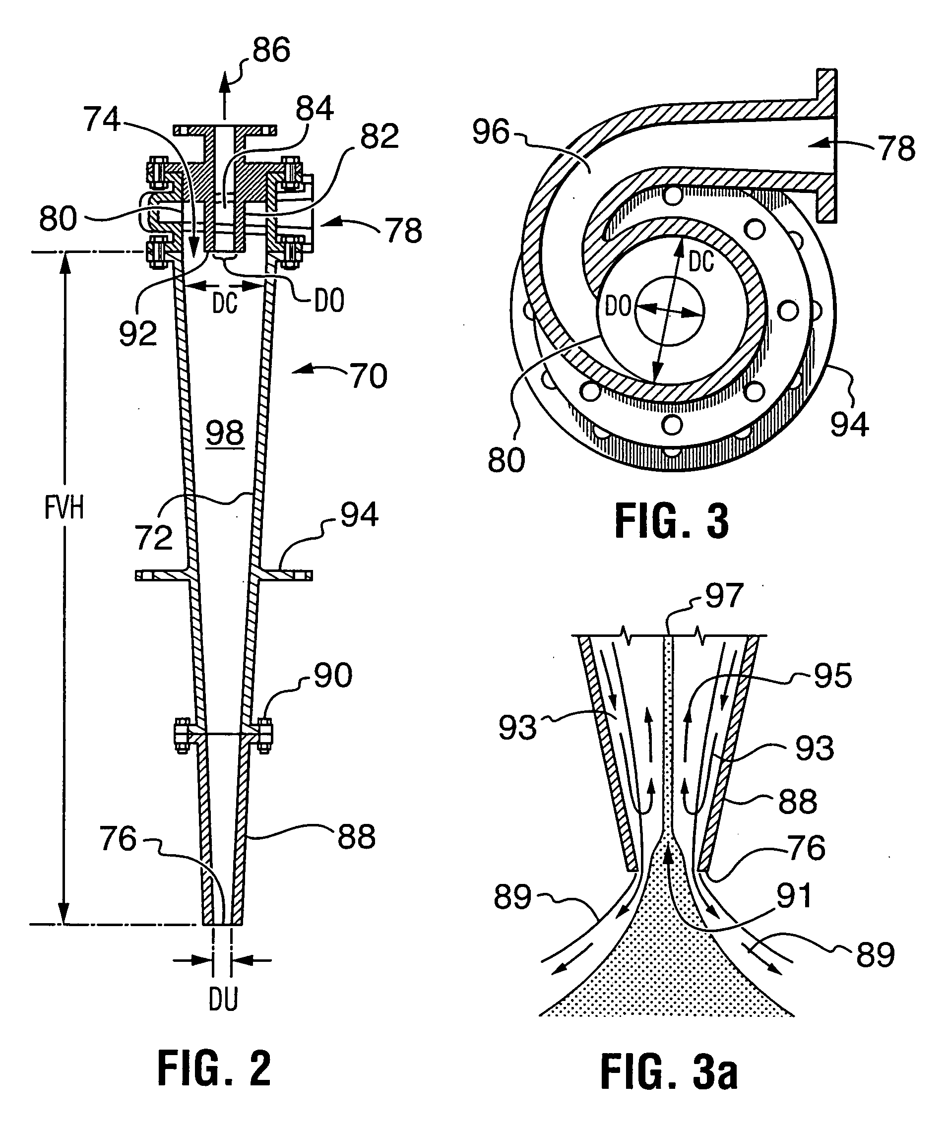
[0029] The hydrocarbon cyclone apparatus of the present invention has a long-body extending between an inlet port and a cyclone apex outlet, to which the output underflow stream is directed, and an abbreviated vortex finder to which the output overflow stream is directed. This configuration permits the cyclone to reject water at a high percentage to the underflow stream output at the apex of the cyclone. This is accomplished in process conditions that achieve a high hydrocarbon recovery to the overflow stream, which is directed to the cyclone vortex finder, while still rejecting most of the water and minerals to the apex underflow stream. Mineral rejection is assisted by the hydrophilic nature of the mineral constituents. The cyclone has a shortened or abbreviated vortex finder, allowing bitumen to pass directly from the input bitumen stream of the cyclone inlet port to the cyclone vortex finder to which the output overflow stream is directed. The long-body configuration of the cyclone facilitates a high water rejection to the apex underflow. Thus, the normally contradictory goals of high hydrocarbon recovery and high rejection of other components are simultaneously achieved.

Problems solved by technology

Centrifuge units require an on-going expense in terms of both capital and operating costs.
Maintenance costs are generally high with centrifuges used to remove water and solid minerals from the bitumen froth.
Consequently, by their very nature, centrifuges require a lot of maintenance and are subject to a great deal of wear and tear.
Additional operating cost results from the power cost required to generate the high g-forces in large slurry volumes.
However, a basic problem is that recovery of bitumen always seems to be compromised by the competing requirements to reject water and solids to tailings while maintaining maximum hydrocarbon recovery.
Cyclone designs heretofore proposed tend to allow too much water content to be conveyed to the overflow product stream yielding a poor bitumen-water separation.
The low water rejection precludes this configuration from being of use in a froth treatment process, as too much of the water in the feed stream is passed to the overflow or product stream.
Without this emulsifier, the slurry can become oil-phase continuous, which will result in several orders of magnitude increase in viscosity.
Unfortunately, these reagents are costly making the process economically unattractive.
The arrangement of Sury introduces process air to effect bitumen recovery and is unsuitable for use in a process to treat deaerated naphtha-diluted-bitumen froth as a consequence of explosion hazards present with naphtha diluents and air.

Method used


Image

  • Bituminous froth hydrocarbon cyclone
  • Bituminous froth hydrocarbon cyclone
  • Bituminous froth hydrocarbon cyclone

Examples


Embodiment Construction

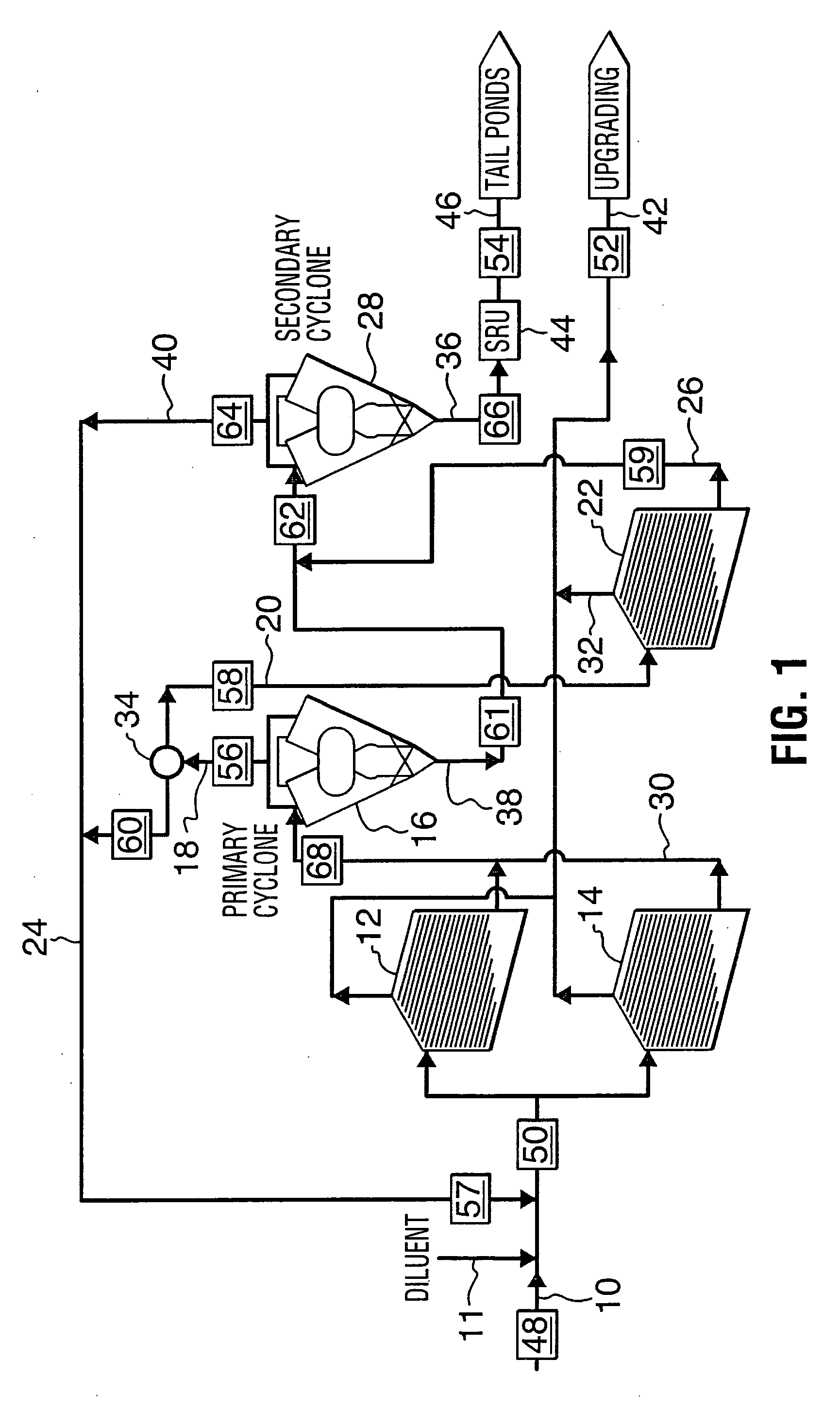
[0038]FIG. 1 is a schematic diagram depicting the arrangement of apparatus adapted to carry out the process of the invention. The schematic diagram provides an outline of the equipment and the process flows, but does not include details, such as pumps, that provide the ability to transport the process fluids from one unit to the next. The apparatus of the invention includes inclined plate separator (IPS) stage units and cyclone stage units, each of which process an input stream to produce an overflow output stream, and an underflow output stream. The IPS overflow output stream has a bitumen enriched content resulting from a corresponding decrease in solids, fines and water content relative to the bitumen content of the IPS input stream. The IPS underflow output stream has solids, fines and water with a depleted bitumen content relative to the IPS input stream. The IPS underflow output stream may be referred to as a bitumen depleted stream. The cyclone stage overflow output stream ha...


PUM

PropertyMeasurementUnit
Lengthaaaaaaaaaa
Lengthaaaaaaaaaa
Fractionaaaaaaaaaa

Abstract

An apparatus to perform a process to remove water and minerals from a bitumen froth output of a oil sands hot water extraction process comprises: (i) a cyclone body having an elongated conical inner surface defining a cyclone cavity extending from an upper inlet region with a diameter DC to a lower apex outlet with a diameter DU; (ii) an inlet means forming an inlet channel extending into the upper inlet region of the cyclone cavity; and (iii) a vortex finder forming an overflow outlet of a diameter (DO) extending into the upper inlet region of the cyclone cavity toward the lower apex outlet and having a lower end extending an excursion distance below the inlet channel; wherein a fluid composition entering the inlet channel into the cyclone cavity is urged by force of gravity and velocity pressure downward toward the lower apex and variations in density of the constituent components of the fluid composition cause the lighter component materials to be directed toward the overflow outlet of the vortex finder.

Description

CROSS REFERENCE TO PRIOR APPLICATIONS [0001] This is a division of U.S. application Ser. No. 10 / 306,003, filed on Nov. 29, 2002, which claims priority from Canadian patent application no. 2,400,258 filed on Sep. 19, 2002.FIELD OF THE INVENTION [0002] This invention relates to bitumen recovery from oil sand and more particularly to a treatment process for the removal of water and mineral from the product produced in a primary oil sand bitumen extraction process. In a particular aspect, the invention relates to a hydrocarbon cyclone for processing a bitumen froth stream. BACKGROUND OF THE INVENTION [0003] Oil sands are a geological formation, which are also known as tar sands or bituminous sands. The oil sands deposits provide aggregates of solids such as sand, clay mineral plus water and bitumen—a term for extra heavy oil. Significant deposits of oil sands are found in Northern Alberta in Canada and extend across an area of more than thirteen thousand square miles. The oil sands form...

Claims


Application Information

Patent Timeline
IPC IPC(8): C02F1/24B03B5/34B03B9/02C10G1/04
CPCB03B5/34B03B9/02B04C5/08C10G1/045C10G1/047
Inventor GARNER, WILLIAM NICHOLASMADGE, DONALD NORMANSTRAND, WILLIAM LESTER
Owner GARNER WILLIAM NICHOLAS
Learn More