Coatings

a technology of coating and surface, applied in the field of coating a surface, can solve the problems of increasing morbidity and mortality, increasing medical costs, and reducing the adhesion or attachment of particles to the modified surface, so as to prevent or minimise the attachment of particles, and reduce the risk of infection.

Active Publication Date: 2006-07-13
DUNDEE UNIV OF THE UNIV COURT OF THE
View PDF0 Cites 77 Cited by
  • Summary
  • Abstract
  • Description
  • Claims
  • Application Information

AI Technical Summary

Benefits of technology

[0012] According to a first aspect of the present invention there is provided a modified surface wherein the adhesion or attachment of particles to the modified surface has been minimised or prevented by adjusting the Lifshitz-van der Waals (LW) surface free energy of an unmodified surface to be equal to or approximately equal to the Lifshitz-van der Waals (LW) surface free energy of particles in an environment surrounding the surface when the modified surface is in use.

Problems solved by technology

A problem which exists in the art is that implanted medical devices are prone to bacterial adhesion and colonization on their surface.
Implanted medical devices are also susceptible to thrombus formation and prion, blood protein and / or other protein formation.
Infections arising from the use of implanted medical devices, such as heart valves, stents, catheters, joint prostheses, intraocular lenses and dental implants etc. are associated with increased morbidity and mortality, prolonged hospitalisation, patient discomfort and increased medical costs.
Progress in the area of anti-microbial treatment has been of limited success.
Due to infection, prosthetic valve endocarditis remains one of the most dangerous and life-threatening complications following heart valve replacement.
However, the currently available antimicrobial coatings have the problems of poor abrasion and poor corrosion resistance, limited biocompatibility and other adverse side effects.
Furthermore, there has been a growing understanding that the generation of wear debris due to friction at articulating surfaces or the release of metal ions can lead to severe cell response and bone resorption or osteolysis, giving rise to premature failure of implants.
Blood contacting devices often suffer from thrombus formation due to limited haemocompatibility.
Despite these favourable results and continuous technical improvements, the application of stents, artificial arteries and vascular catheters etc. is still limited by subacute occlusion and restenosis due to thrombus formation, especially in low flow and stagnation zones.
However, diamond-like carbon coatings cannot inhibit blood protein adhesion to their surfaces significantly.
However, the stains on the surfaces of surgical devices from contamination are not easily removed.
Prion (a microscopic protein particle similar to a virus but lacking nucleic acid, thought to be the infectious agent responsible for scrapie and certain other degenerative diseases of the nervous system) diseases constitute a unique infection control problem because prions exhibit unusual resistance to conventional chemical and physical decontamination methods.
So far no attempts have been made to develop CJD-resistant surgical instruments.

Method used


Image

  • Coatings
  • Coatings

Examples


example 1

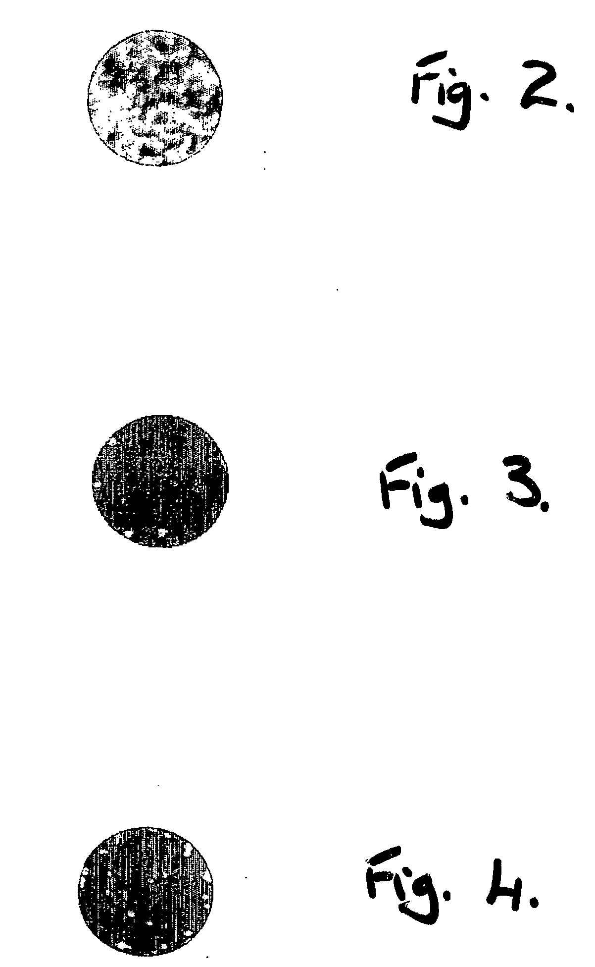
[0067]FIG. 3 is a microscope image of the amount of bacteria found on a surface of a medical device with a coating of modified diamond-like carbon which comprises about 4% fluorine. There is a bacteria density of 407 cells / cm2. A combined radio frequency (rf) plasma and magnetron sputtering technique is used to form the coating which is about 2 micrometers thick.

example 2

[0068]FIG. 4 is a microscope image of the amount of bacteria found on a surface of a medical device with a Ag—PTFE-C20H20F23N2O4 surfactant coating of about 4 micrometers thick. The ratio of Ag:PTFE:surfactant is 75%:22%:3% by weight. There is a bacteria density of 614 cells / cm2.

[0069] To form this coating the following electroless plating technique is used:

ProceduresConditions1.Alkaline cleaningNaOH: 20˜30 g / l; Na2CO3: 25˜30g / l; Na3PO4: 25˜35 g / l;Na2SiO3: 5˜10 g / l;Temperature: 60˜80° C., Time:5˜10 min.2.RinsingWith water. Room temperature.3.Cathodic electrocleaningNaOH: 25˜35 g / l; Na2CO3: 25˜30g / l; Na3PO4: 25˜35 g / l;Na2SiO3: 5˜10 g / l; voltage: 5˜7V; Room temperature; Time:2˜3 min.4.RinsingWith water. Room temperature.5.PicklingHCl (30%): H2O = 1:1; Roomtemperature. Time: 0.5˜1 min.6.Activation (to coat aNiCl2.6H2O: 200˜400 g / l; HClsuper-thin layer Ni)(30%): 75˜200 ml / litre;Anode plates: Ni; Cathodiccurrent: 2˜3 A / dm2; Roomtemperature; Time: 1 min.7.Electroless plating Ni—PNiCl2....

example 3

[0070] The following electroless plating technique is used to form a coating of Ni—Cu—P—PTFE nano-composite. The ratio of Ni:Cu:P:PTFE is 80%:11%:4%:5% by weight.

ProceduresConditions1.Alkaline cleaningNaOH: 20˜30 g / l; Na2CO3: 25˜30g / l; Na3PO4: 25˜35 g / l;Na2SiO3: 5˜10 g / l;Temperature: 60˜80° C.,Time: 5˜10 min.2.RinsingWith water. Room temperature.3.Cathodic electrocleaningNaOH: 25˜35 g / l; Na2CO3: 25˜30g / l; Na3PO4: 25˜35 g / l;Na2SiO3: 5˜10 g / l; voltage:5˜7 V; Room temperature;Time: 2˜3 min.4.RinsingWith water. Room temperature.5.PicklingHCl (30%): H2O = 1:1; Roomtemperature. Time: 0.5˜1 min.6.Activation (to coat aNiCl2.6H2O: 200˜400 g / l; HClsuper-thin layer Ni)(30%): 75˜200 ml / litre;Anode plates: Ni; Cathodiccurrent: 2˜3 A / dm2; Roomtemperature; Time: 1 min.7.Electroless plating Ni—PNiCl2.6H2O: 20˜30 g / l;Na3C6H5O7.6H2O: 15˜30 g / l;NaH2PO2: 15˜35 g / l; C3H6O3:20˜30 g / l; Temperature: 85˜90°C.; pH: 4.6˜5.08.RinsingWith water. Room temperature.9.Electroless plating with85˜90° C., pH: 4.8˜5....


PUM

PropertyMeasurementUnit
pressureaaaaaaaaaa
temperatureaaaaaaaaaa
thicknessaaaaaaaaaa

Abstract

This invention relates to coating a surface wherein the coated surface inhibits foulants such as cell and / or protein and / or prion adhesion or formation. In particular, the coated surface may be part of a medical device which inhibits bacterial adhesion and colonisation, thrombus formation and / or prion, blood protein and / or protein formation.

Description

FIELD OF THE INVENTION [0001] This invention relates to coating a surface wherein the coated surface inhibits foulants such as cell and / or protein and / or prion adhesion or formation. In particular, the coated surface may be part of a medical device which inhibits bacterial adhesion and colonization, thrombus formation and / or prion, blood protein and / or other protein formation. BACKGROUND OF THE INVENTION [0002] A problem which exists in the art is that implanted medical devices are prone to bacterial adhesion and colonization on their surface. Implanted medical devices are also susceptible to thrombus formation and prion, blood protein and / or other protein formation. [0003] Infections arising from the use of implanted medical devices, such as heart valves, stents, catheters, joint prostheses, intraocular lenses and dental implants etc. are associated with increased morbidity and mortality, prolonged hospitalisation, patient discomfort and increased medical costs. Progress in the are...

Claims


Application Information

Patent Timeline
Patent Type & Authority Applications(United States)
IPC IPC(8): C09D1/00C07F7/18C09J11/06B32B9/00A61L27/30A61L29/10A61L31/08A61L33/02C23C16/26
CPCA61L27/30A61L27/303A61L29/10A61L29/103A61L31/08Y10T428/24942A61L33/02A61L33/025C23C16/26Y10T428/30A61L31/084Y10T428/31678
Inventor ZHAO, QIABEL, ERIC
Owner DUNDEE UNIV OF THE UNIV COURT OF THE
Why Eureka
Try Eureka