Hollow fiber membrane submodule and module including the same

a technology of hollow fiber membrane and submodule, which is applied in the field of hollow fiber membrane submodule, can solve the problems of inability to test and/or examine the open surface of hollow fiber membrane for leakage, disadvantageous in ecology and cost efficiency and the cost of pressure vessel is reduced. , the effect of reducing the number of pipes

Active Publication Date: 2006-07-13
TOYOBO CO LTD
View PDF8 Cites 17 Cited by
  • Summary
  • Abstract
  • Description
  • Claims
  • Application Information

AI Technical Summary

Benefits of technology

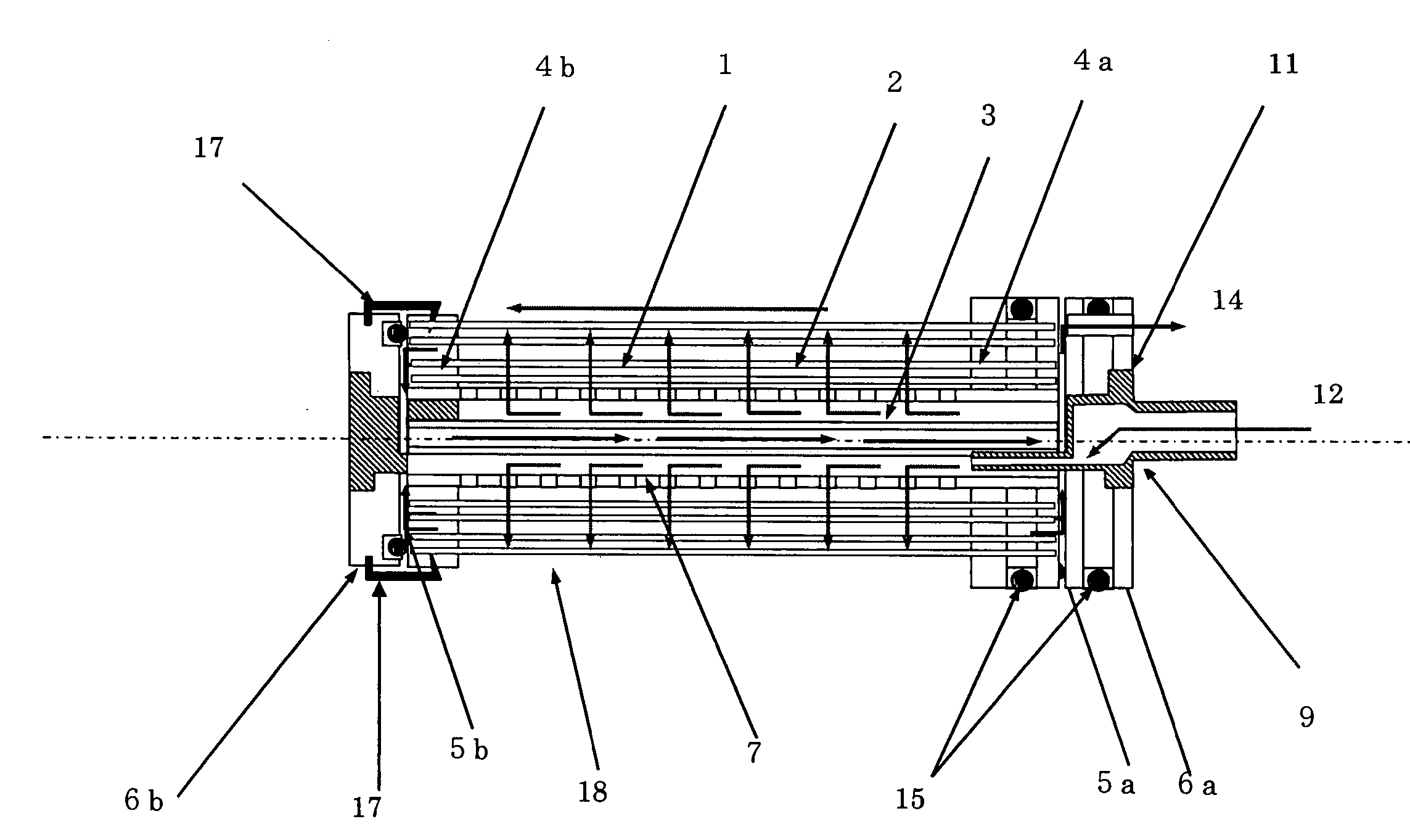
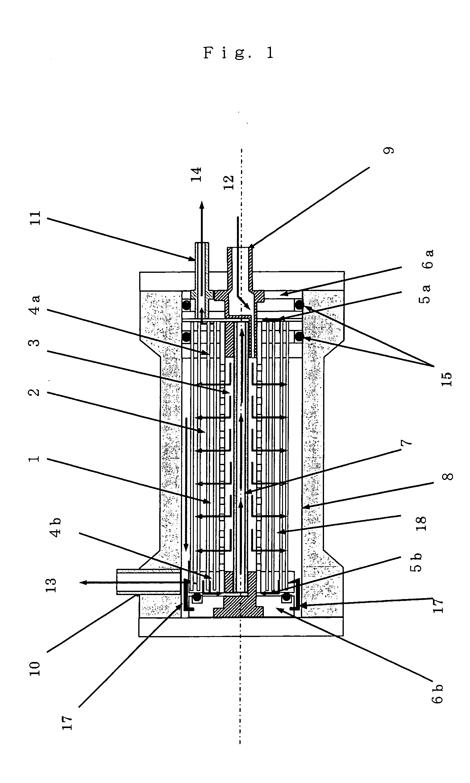
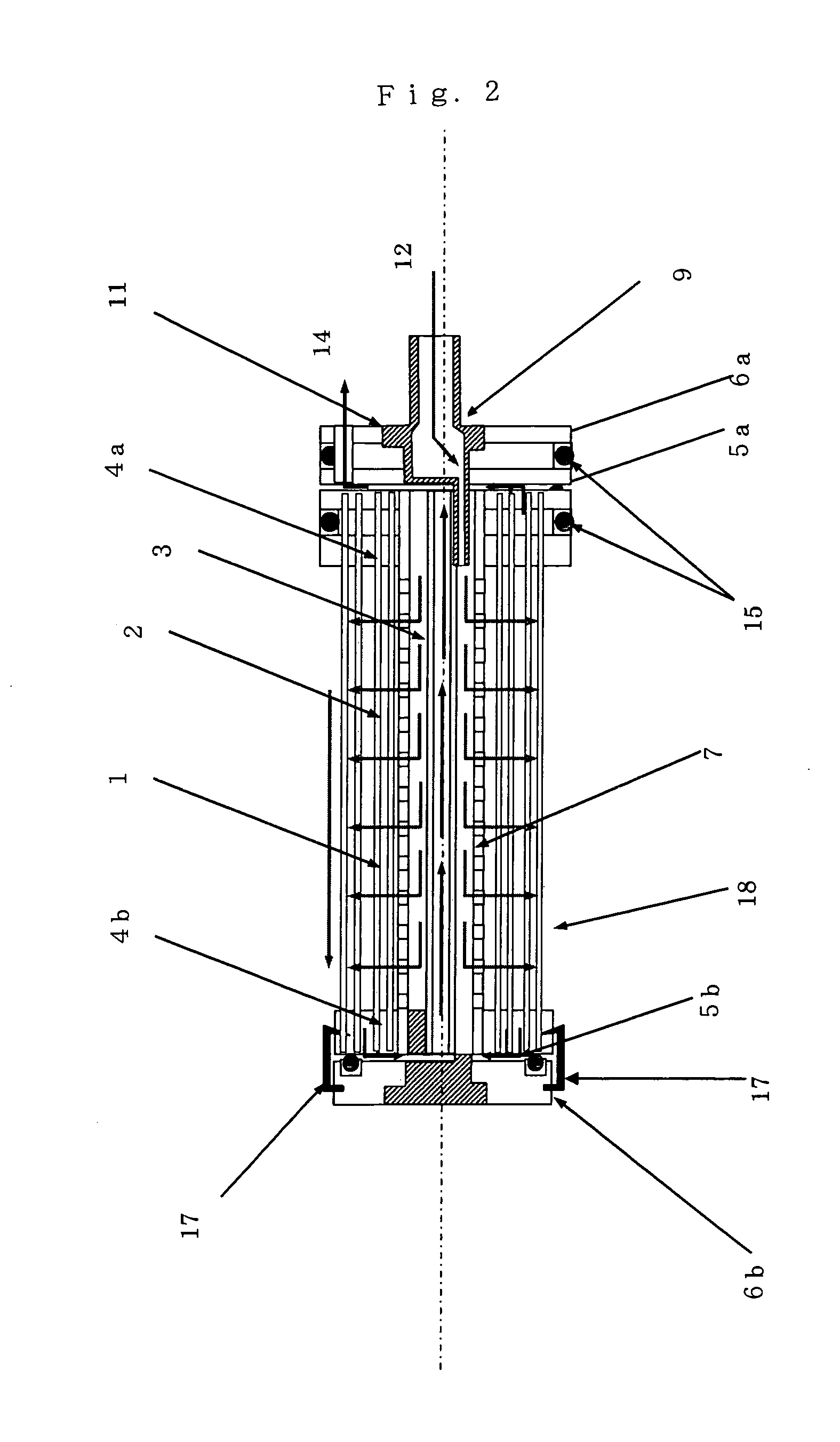
[0019] In the present invention, the expression that both ends of the hollow fiber membrane assembly of the invention are separately fixed with resin, and at least one end of the hollow fiber membrane assembly is subsequently cut to hollow out the hollow fiber membranes means that both ends of the hollow fiber membrane assembly are separately fixed and hermetically sealed with an adhesive resin by potting or the like, so as to prevent leakage of the feed fluid from the spaces among the hollow fiber membranes or spaces among the hollow fiber membranes and resin. The adhesive resin used is preferably selected from epoxy resins, urethan resins, silicon resins and the like according to the properties of the fluid to be treated and the conditions of use. The ends of the hollow fiber membrane assembly fixed with an adhesive are opened by cutting or other process such that the hollow fiber membranes are hollowed out, so as to form a hollow fiber membrane element. One or a plurality of hollow fiber membrane submodules are installed in a pressure vessel having a feed fluid inlet, a concentrated fluid outlet, and a permeated fluid outlet, thus forming a hollow fiber membrane module.
[0034] A plurality of hollow fiber membrane submodules are preferably connected in series when the recovery rate is high, or when the concentrations of permeated fluids from the respective hollow fiber membrane submodules should be different. In serial connection, a feed fluid is fed to each of the hollow fiber membrane submodules sequentially from an upstream submodule's feed side and concentration side to a downstream submodule's feed side and concentration side within a single pressure vessel. The composition and flow rate of the feed fluid basically vary in each hollow fiber membrane submodule. As the feed fluid travels to the downstream submodule, the concentration of non-permeated constituents, i.e., constituents to be removed, in the feed fluid increases, and the flow rate decreases. Accordingly, the permeated fluids obtained from the respective hollow fiber membrane submodules usually differ in flow rate and concentration, depending on the operating conditions of the hollow fiber membrane module and the recovery rate in particular. A hollow fiber membrane submodule situated closer to the concentration side has a lower flow rate of the permeated fluid, with an increase in the concentration of non-permeated constituents, i.e., constituents to be removed from the feed fluid. The permeated fluids obtained from the respective hollow fiber membrane submodules have different concentrations, so that overall optimization can be achieved by, for example, post-treating only the permeated fluid from the hollow fiber membrane submodule having a high concentration of the permeated fluid. Moreover, in such a serial connection, the flow rate of the feed fluid fed to each hollow fiber membrane submodule is high, and accordingly the flow velocity of the feed fluid on the hollow fiber membrane surfaces is great even at a high recovery rate. This effectively prevents concentration polarization and the adherence of contaminants to the membrane surfaces.

Problems solved by technology

However, a problem with this hollow fiber membrane submodule is that because the permeated fluid collectors are attached to the hollow fiber membrane element by bonding or the like, the entire hollow fiber membrane submodule has to be replaced when replacing the membrane.
Accordingly, the permeated fluid collectors are also disposed and replaced, and thus cannot be reused, which is disadvantageous in terms of ecology and cost efficiency.
Moreover, because the permeated fluid collectors are not removable, if the submodule proves to be defective after performance evaluation, the open surfaces of the hollow fiber membranes cannot be tested and / or examined for leaks, or cannot be repaired.
In addition, with a large hollow fiber membrane element, direct installation of permeated fluid collectors or end caps into the element is difficult.
The disadvantage of this configuration, however, is that during membrane treatment operation, the screws may become loose by the vibration of the pump feeding a feed fluid to the hollow fiber membrane submodule.
Moreover, although metal is a preferable material for the screws of this configuration, the metal is subjected to corrosion in treating such liquids as seawater, and therefore is not preferable.

Method used


Image

  • Hollow fiber membrane submodule and module including the same
  • Hollow fiber membrane submodule and module including the same
  • Hollow fiber membrane submodule and module including the same

Examples


example 1

[0104] (Fabrication of Hollow Fiber Membranes)

[0105] Forty parts by weight of cellulose triacetate (acetylation degree: 61.4) was mixed with a solution composed of 18 parts by weight of ethylene glycol and 42 parts by weight of N-methyl-2-pyrrolidone, and the mixture was heated to obtain a solution for forming membranes. The solution was degassed under reduced pressure, and then discharged from a nozzle to travel through the air into a coagulating liquid composed of 65 parts by weight of water at 14° C., 10.5 parts by weight of ethylene glycol and 24.5 parts by weight of N-methyl-2-pyrrolidone, to thereby form hollow fibers. Subsequently, the hollow fiber membranes were washed with water at room temperature to remove excess solvent and nonsolvent, and then treated with hot water. Thus, hollow fiber reverse osmosis membranes made of cellulose triacetate membranes were produced. The obtained hollow fiber membranes had an outside diameter of 137 Mm and an inside diameter of 53 μm. The...

example 2

[0111] Hollow fiber membranes and a hollow fiber membrane element were fabricated in a similar manner to Example 1, and components such as a permeated fluid collector and the like were then attached to the hollow fiber membrane element to form a hollow fiber membrane submodule. Two such hollow fiber membrane submodules were installed in a pressure vessel with an intermediate connector therebetween. A double-type module having a parallel arrangement as that shown in FIG. 5 was thus fabricated. Reverse osmosis treatment was carried out under similar conditions to Example 1. As a result, the salt rejection ratio was 99.5%. Moreover, as in Example 1, after the removal of the hollow fiber membrane submodules from the hollow fiber membrane module, the permeated fluid collector was readily installed in and removed from each of the hollow fiber membrane submodule using a jig. Furthermore, the module was tested for back pressure resistance under a pressure of 2 kg / cm2 for a back flow phenome...

example 3

[0112] Hollow fiber membranes and a hollow fiber membrane element were fabricated in a similar manner to Example 1, and then a permeated fluid collector was secured to each end of the element with snaps in engagement therebetween. A hollow fiber membrane submodule as shown in FIG. 6 was thus fabricated. Two such hollow fiber membrane submodules were installed in a pressure vessel with an intermediate connector therebetween, so as to fabricate a double-type module having a parallel arrangement as that shown in FIG. 7. Reverse osmosis treatment was carried out under similar conditions to Example 1. As a result, the salt rejection ratio was 99.5%. Moreover, as in Example 1, after the removal of the hollow fiber membrane submodules from the hollow fiber membrane module, the permeated fluid collectors were readily installed in and removed from each of the hollow fiber membrane submodules using a jig. Furthermore, the module was tested for back pressure resistance under a pressure of 2 kg...


PUM

PropertyMeasurementUnit
winding angleaaaaaaaaaa
diameteraaaaaaaaaa

Abstract

The present invention provides a hollow fiber membrane submodule comprising a hollow fiber membrane element, permeated fluid collectors, and snaps for securing the permeated fluid collectors to the hollow fiber membrane element, wherein the permeated fluid collectors are closely attached to the hollow fiber membrane element with the snaps in engagement therebetween and being arranged non-continuously around the outer periphery of each permeated fluid collector, and the permeated fluid collectors can be removed from and installed in the hollow fiber membrane element. With the hollow fiber membrane submodule of the present invention, when replacing the membranes, the hollow fiber membrane element is replaced with a new hollow fiber membrane element, and then the permeated fluid collectors can be reattached to the replaced element and reused. In addition, the snaps are capable of positioning the hollow fiber membrane element at the center of the hollow fiber membrane submodule within a pressure vessel, and also defining a flow path of a concentrated fluid with its non-continuous arrangement.

Description

TECHNICAL FIELD [0001] The present invention relates to a hollow fiber membrane submodule for forming a hollow fiber membrane module comprising hollow fiber membranes having selective permeability. The present invention relates to a hollow fiber membrane module comprising hollow fiber membranes having selective permeability, the module being applicable to membrane separation treatment of fluids, such as, for example, desalination of sea water, desalination of brackish water, purification of wastewater, production of sterile water, production of ultrapure water, and like reverse osmosis processes; advanced water purification treatment, removal of low-molecular-weight toxic substances such as agricultural chemicals, odorants and disinfection by-product precursors, water softening treatment by removal of hardness constituents, and like nanofiltration processes; recovery of paint from electrodeposition coating wastewater, concentration and / or recovery of useful food-related materials, w...

Claims


Application Information

Patent Timeline
Patent Type & Authority Applications(United States)
IPC IPC(8): B01D63/06B01D61/08B01D63/02B01D63/04B01D65/00
CPCB01D63/02B01D63/043B01D65/00B01D2313/06B01D2313/20Y02A20/131
Inventor MARUI, KATSUSHIGEKOTERA, HIDETOKUMANO, ATSUO
Owner TOYOBO CO LTD
Why Eureka
Try Eureka