
Infrared shielding material microparticle dispersion infrared shield, process for producing infrared shield material microparticle and infrared shielding material microparticle

a technology of infrared shielding and microparticles, which is applied in the direction of manufacturing tools, radiation-absorbing paints, wire tools, etc., can solve the problems of high temperature exposure of the substrate used for heat ray cut-off materials, limited application, and increased cost, and achieve excellent characteristics and efficient shielding

Active Publication Date: 2006-08-10
SUMITOMO METAL MINING CO LTD
View PDF7 Cites 138 Cited by
  • Summary
  • Abstract
  • Description
  • Claims
  • Application Information

AI Technical Summary

Benefits of technology

[0068] According to the present invention, fine particles of infrared-shielding material containing the tungsten oxide fine particles and / or the tungsten oxide composite fine particles are finely granulated to a particle size of not less than 1 nm and not more than 800 nm. The fine particles of infrared-shielding material thus obtained is dispersed in a medium, and a fine particle dispersion of infrared-shielding material can be fabricated, having excellent characteristics such as efficiently shielding the sunbeam, especially the light in the near-infrared region, while holding a transmittance to the visible region, compared to the film fabricated by a dry method including a vacuum deposition method such as a sputtering method, a vapor deposition, an ion- plating and a chemical vapor deposition (CVD), or the film made by CVD and spraying. In addition, when producing the infrared-shielding body by using the fine particle dispersion of infrared-shielding material, an inexpensive infrared-shielding body can be produced without using a large-scale apparatus such as a vacuum apparatus, and an industrially useful infrared-shielding dispersion material is thereby obtained.

Problems solved by technology

Thus, when the pigment is used in a window material or the like, the window material tends to have dark colors, and therefore the application is limited.
Therefore, when used outside, such a half-mirror tends to glare due to reflection, posing a problem visually.
These production methods require a large scale apparatus and thus a cost is increased.
Also, the substrates used for these heat ray cut-off materials are exposed to high temperature plasma and may require heating after film deposition.

Method used


Image

  • Infrared shielding material microparticle dispersion infrared shield, process for producing infrared shield material microparticle and infrared shielding material microparticle
  • Infrared shielding material microparticle dispersion infrared shield, process for producing infrared shield material microparticle and infrared shielding material microparticle
  • Infrared shielding material microparticle dispersion infrared shield, process for producing infrared shield material microparticle and infrared shielding material microparticle

Examples


example 1

[0116] Tungsten hexachloride and copper dichloride were each weighed so that the molar ratio of W to Cu was 1:0.2. Each compound was dissolved in small portions in ethanol to obtain a mixture solution. The mixture solution was dried at 130° C. to obtain a starting material in a powder form. This starting material was heated at 550° C. in a reductive atmosphere (argon / hydrogen=95 / 5 by volume) for 1 hour, then cooled to room temperature, and heated at 800° C. for one hour in an argon atmosphere, thus producing powder of Cu0.2WO2.72. An X-ray diffraction crystallography performed on the resultant Cu0.2WO2.72 revealed the presence of crystalline phase of W18O49. The specific surface area of Cu0.2WO2.72 was 30 m2 / g.

[0117] 20 pts. wt. Cu0.2WO2.72 powder thus formed, 75 pts. wt. toluene, and 5 pts. wt. polyacrylate-based dispersant were mixed, and subjected to dispersion processing, to obtain a dispersion solution (solution A) in which the average dispersed particle diameter was 80 nm. 10...

example 2

[0121] Tungsten hexachloride was dissolved in small portions in ethanol to obtain a solution. The solution was dried at 130° C., to obtain the starting material in a powder state. This starting material was heated at 550° C. in a reductive atmosphere (argon / hydrogen=95 / 5 by volume) for 1 hour, and cooled to room temperature once, then heated for one hour at 800° C. in an argon atmosphere. Powder of W18O49(WO2.72) was thus produced.

[0122] An X-ray diffraction crystallography performed on the resultant WO2.72 revealed the presence of crystalline phase of W18O49. The specific surface area of WO2.72 was 30 m2 / g.

[0123] 20 pts. wt. WO2.72 powder thus formed, 75 pts. wt. toluene, and 5 pts. wt. polyacrylate-based dispersant were mixed, and subjected to dispersion processing, to obtain a dispersion solution (solution B) in which the average dispersed particle diameter was 80 nm. 10 pats. wt. solution B thus formed and 100 pats. wt. UV-curable hardcoat resin (solid component=100%) were mix...

example 3

[0125] Tungsten hexachloride and copper dichloride were each weighed so that the molar ratio of W to Cu was 1:0.2. Each compound was dissolved in small portions in ethanol to obtain a mixture solution. The mixture solution was dried at 350° C. in the atmosphere to obtain the starting material in a powder state. This starting material was heated at 980° C. in an argon atmosphere for 15 hours to produce the powder of Cu0.2WO2.72. The specific surface area of Cu0.2WO2.72 powder was 31 m2 / g.

[0126] 20 pts. wt. Cu0.2WO2.72 powder thus obtained, 75 pts. wt. toluene, and 5 pts. wt. polyacrylate-based dispersant were mixed, and subjected to dispersion processing, to obtain a dispersion solution (solution C) in which the average dispersed particle diameter was 80 nm. 10 pats. wt. solution C thus obtained and 100 pts. wt. UV-curable hardcoat resin (solid component=100%) were mixed to obtain the fine particle dispersion solution of the infrared-shielding material. Using a bar coater, this infr...


PUM

PropertyMeasurementUnit
Temperatureaaaaaaaaaa

Abstract

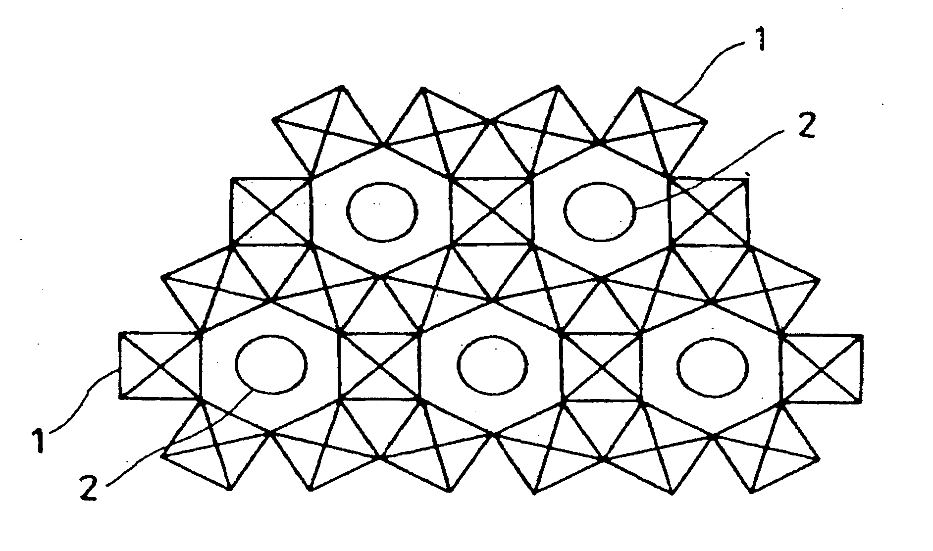
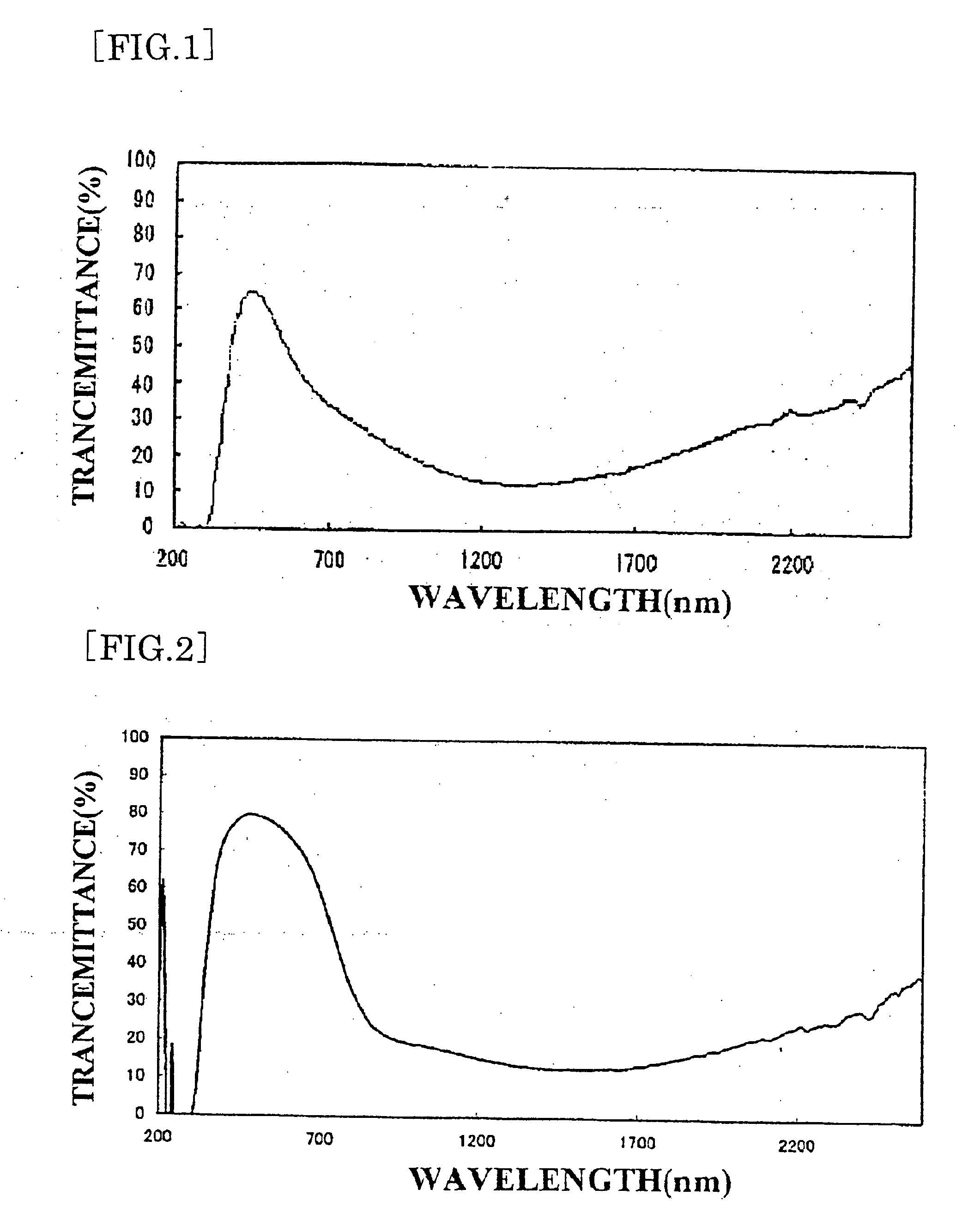
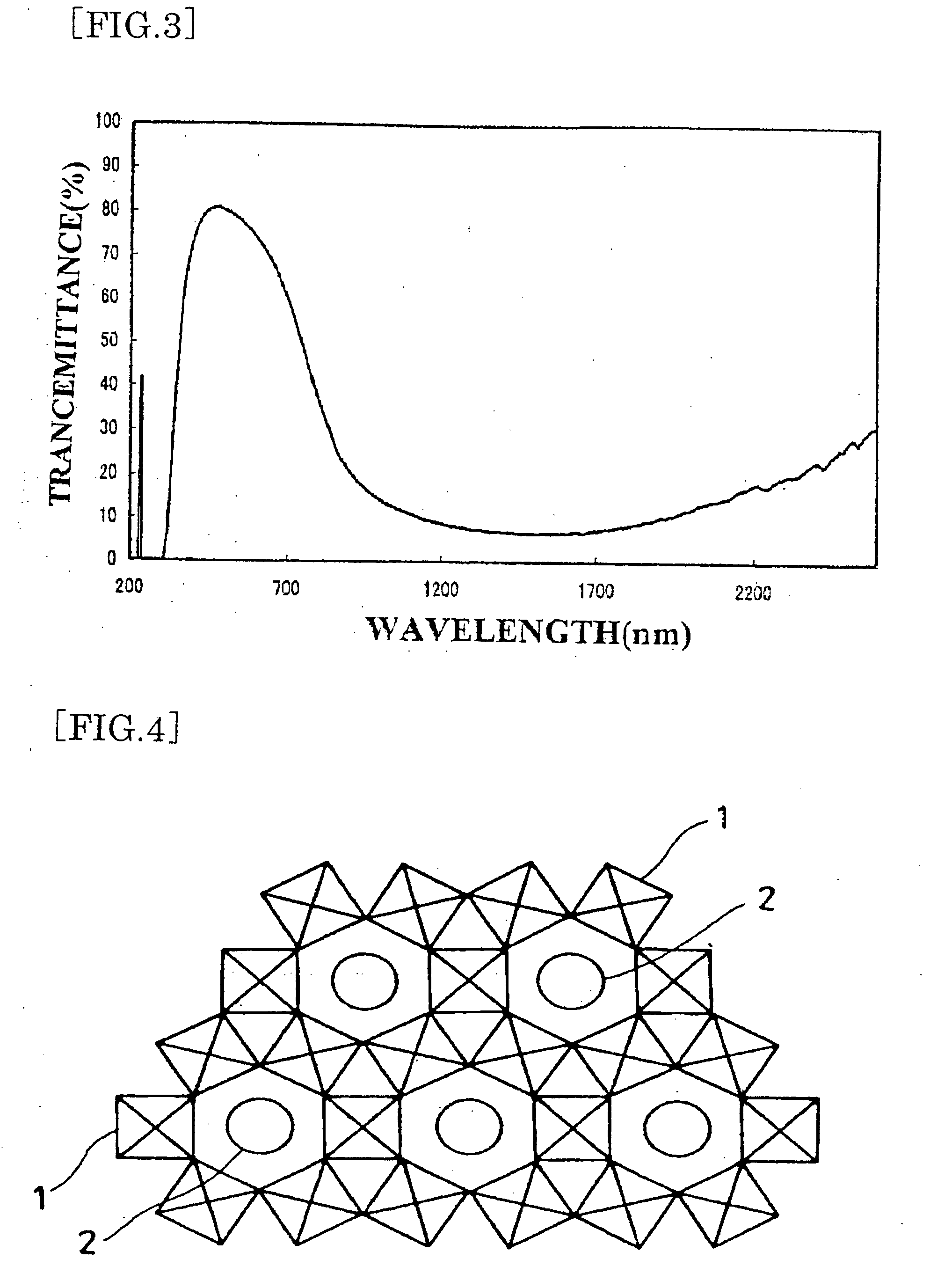
To provide an infrared-shielding body sufficiently transmitting visible rays, having no half-mirror shaped appearance, requiring no large-scale apparatus when forming a film on a substrate, efficiently shutting invisible near-infrared rays with wavelength range of 780 nm or more, while eliminating a heat treatment at high temperature after film formation, and having a spectral characteristic such as transparency with no change of color tone. The starting material, which is a mixture containing a predetermined amount of a tungsten compound, is heated at 550° C. in a reductive atmosphere for 1 hour, then cooled to room temperature once in an argon atmosphere, thus producing powder of W18O49. Then, the powder, the solvent, and the dispersant are mixed, then subjected to dispersion treatment to obtain a dispersion solution. The dispersion solution and a UV-curable hardcoat resin are mixed to obtain a solution of fine particle dispersion of infrared-shielding material. The solution of the fine particle dispersion of infrared-shielding material is applied on a PET resin film to form a film, which is then cured, and an infrared-shielding film having a transmission profile shown in the figure is thereby obtained.

Description

TECHNICAL FIELD [0001] The present invention relates to a fine particle dispersion of infrared-shielding material with fine particles of an oxide material which is transparent in a visible region and having an absorption in a near-infrared-shielding region dispersed in a medium, an infrared shielding-body produced by the fine particle dispersion of infrared-shielding material, a production method of fine particles of infrared-shielding material used for the fine particle dispersion of infrared-shielding material, and fine particles of infrared- shielding material produced by the production method of fine particles of infrared-shielding material. Specifically, the present invention relates to the fine particle dispersion of infrared-shielding material formed by dispersing the fine particles of infrared shielding material containing fine particles of tungsten oxides and / or tungsten oxide composite in the medium. BACKGROUND ART [0002] Patent document 1 proposes a light shielding film u...

Claims


Application Information

Patent Timeline
IPC IPC(8): C04B35/00B29D11/00C01G41/00C01G41/02C09C1/00C09D5/32
CPCC01G41/00C01G41/02C01P2002/82Y10T428/256C09C1/00C09D5/32C01P2006/60
Inventor TAKEDA, HIROMITSUADACHI, KEOJI
Owner SUMITOMO METAL MINING CO LTD
Learn More