Diamond film coated tool and process for producing the same

Active Publication Date: 2006-09-28
SUMITOMO ELECTRIC IND LTD
View PDF8 Cites 27 Cited by
  • Summary
  • Abstract
  • Description
  • Claims
  • Application Information

AI Technical Summary

Benefits of technology

[0042] Preferably, the diamond is applied to the carburized substrate by means of an ultrasonic wave. This allows the diamond to be applied on the substrate firmly with high density.
[0043] In its fourth aspect of the method, the present invention provides a method of manufacturing a diamond coated tool, further comprising an acid treatment step for treating the substrate surface with an acid to partially remove the binding phase metal, the acid treatment step being interposed between the carburization step and the diamond application step. This acid treatment decreases the binding phase metal in the substrate surface to improve adhesion of the diamond coating to the substrate.
[0044] Particularly preferably, the method of manufacturing the diamond coated tool according to the present invention comprises a combination of the partial removal of the binding phase metal and the diamond application as described above. That is, this preferred method of the present invention comprises subjecting the carburized substrate surface to the acid treatment to partially remove the binding phase metal, applying a diamond powder on the substrate surface, placing the substrate in hot-filam

Problems solved by technology

However, in spite of such reduction in grain size, a problem may arise in that neither a work surface roughness nor a working precision is improved significantly.
In this regard, it is assumed that since the diamond coating gives a roundness to the cutting edge of a tool like the case of coarse grains and makes the edge surface itself too smooth, the tool may have an inadequate engagement to the work to cause its chatter or its unexpected disengagement or relief.
Besides, for semi-dry cutting using only a very little quantity of coolant during working, although it is necessary to efficiently supply a coolant to a sp

Method used


Image

  • Diamond film coated tool and process for producing the same
  • Diamond film coated tool and process for producing the same
  • Diamond film coated tool and process for producing the same

Examples


embodiment 1

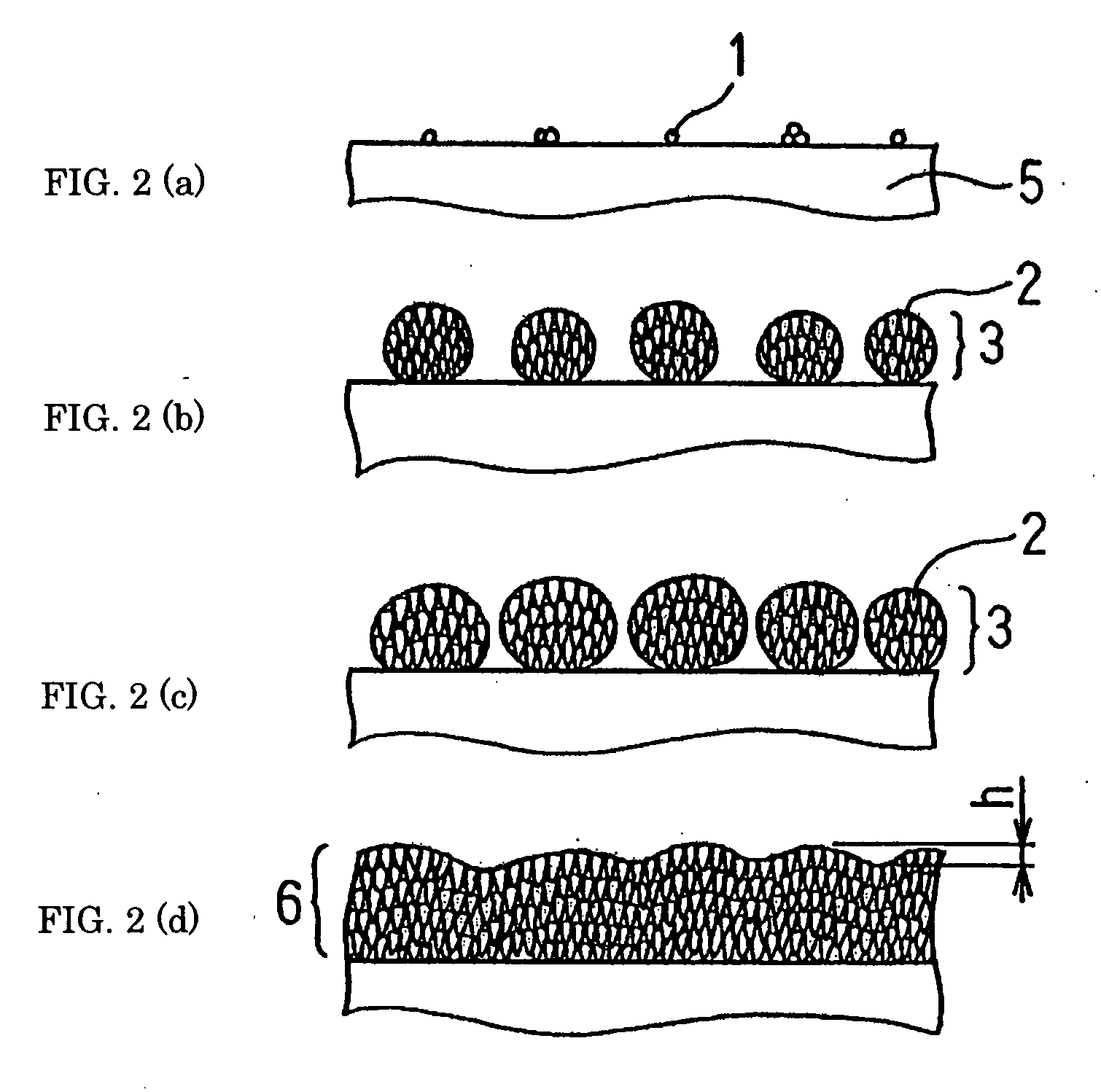
[0068] In order to validate the effectiveness of conditions for generation of polycrystalline diamond aggregate3 which is requisite constituent elements of the present invention, a strip of cemented carbide (10×10×1t (mm)) containing 5 mass % of Co was prepared as a substrate 5, and an experiment was conducted to coat the substrate with diamond film. The prepared substrates 5 included carburized substrates and non-carburized ones. For the carburization, the substrate was placed in hot-filament CVD equipment and processed for 6 hours in a 1 vol. % methane-hydrogen mixed gas atmosphere at an ambient temperature of about 900° C. under pressure of 13.0 kPa. The magnitude of saturation magnetization of the carburized substrate was 97.5-98.5 G-cm3 / g, while the non-carburized substrate had a saturation magnetization of 80-83G-cm3 / g.

[0069] Then, these substrates were coated with diamond by growing the diamond to a thickness of 10 micrometers under five varied magnitudes of synthesizing pre...

embodiment 2

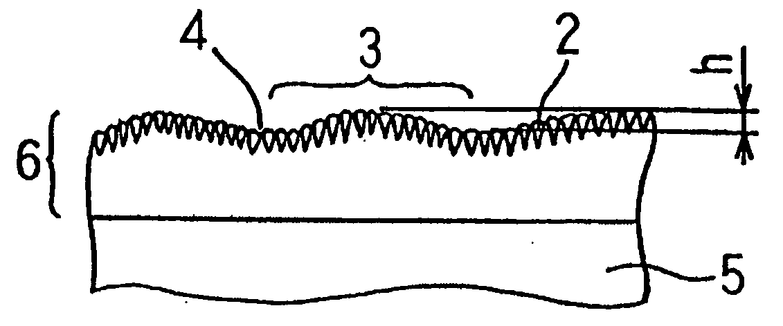
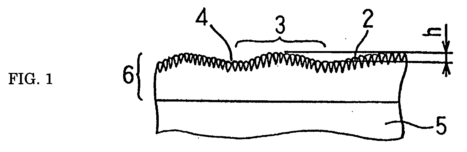
[0070] In order to determine the difference in tool performance by the extent of undulation h of the surface of a diamond coating (See FIG. 1), an end mill with a diameter of 8 mm was made and its performance was evaluated. A cemented carbide containing 5 mass % of Co was used as a substrate. This substrate was placed in hot-filament CVD equipment and processed therein for carburization for 6 hours in a 1 vol. % methane-hydrogen mixed gas atmosphere at an ambient temperature of about 900° C. under pressure of 13.0 kPa. Then, the substrate was coated with diamond so that the diamond coating grew to about 20 micrometers in thickness. The coating was formed of diamond aggregates and the average grain size of diamond was in the range of about 1.0-1.5 micrometers in all specimens. The grain boundaries of diamond formed grooves.

[0071] The diamond coating was formed using hot-filament CVD equipment with its process conditions including a hydrogen flow rate of 1,700 sccm, methane flow rate...

embodiment 3

[0081] In order to determine the difference in tool performance by RMS values observed on the surface of diamond coating, an end mill with a diameter of 8mm was made and its performance was evaluated. A cemented carbide containing 5 mass % of Co was used as a substrate. This substrate was placed in hot-filament CVD equipment and processed therein for carburization for 6 hours in a 1 vol. % methane-hydrogen mixed gas atmosphere at an ambient temperature of about 900° C. under pressure of 13.0 kPa. Then, the substrate was coated with diamond so that the diamond coating grew to about 20 micrometers in thickness.

[0082] The resultant coating was formed of diamond aggregates and the average grain size of diamond was in the range of about 0.7-1.0 micrometers in all specimens. The diamond coating 6 was formed using hot-filament CVD equipment with its process conditions including a hydrogen flow rate of 1,700 sccm, methane flow rate of 45 sccm, synthesizing pressure of 3.9 kPa, filament tem...


PUM

PropertyMeasurementUnit
Grain sizeaaaaaaaaaa
Fractionaaaaaaaaaa
Fractionaaaaaaaaaa

Abstract

The invention provides a diamond coated tool having an excellent cutting performance, wear resistance, adhesion resistance and work surface roughness in combination and a method of producing such a tool. A diamond coated tool comprising a substrate and a diamond coating formed on the surface of the substrate, wherein said substrate is made of a cemented carbide or a cermet, diamond grains constituting a growth surface of said diamond coating has an average grain size of about 1.5 micrometers or below, said diamond coating has a thickness ranging from about 0.1 micrometer to 20 micrometers, and said diamond coating has an average surface roughness Ra ranging from about 0.01 micrometer to 0.2 micrometer. Such a diamond coated tool can be obtained by carburizing the substrate consisting of a cemented carbide or a cermet, and growing up a diamond coating thereon.

Description

TECHNICAL FIELD [0001] The present invention relates to diamond coated tools used as cutting tools, wear-resistant tools, adhesion-resistant tools, etc. and a method of manufacturing such tools. More specifically, the tool of the present invention is used in such fields of application as working of aluminum alloys or magnesium alloys involving difficult machinability and requiring lower roughness of work surfaces, drilling of glass-reinforced epoxy resins or like materials requiring sharpness and adhesion resistance of major cutting edges, semi-dry cutting, or tools for IC or LSI packages fabrication including bending or cutting of outer leads in semiconductor equipment. BACKGROUND ART [0002] Heretofore, are known cutting tools, wear-resistant tools and the like employing as their substrate a cemented carbide or ceramics such as silicon nitride or silicon carbide and having their substrates coated with a diamond film in order to improve the wear resistance and adhesion resistance. G...

Claims


Application Information

Patent Timeline
IPC IPC(8): B32B9/00B32B19/00C23C16/00B05D3/00B23G5/06C23C16/02C23C16/27
CPCB23G5/06B23G2200/26B23G2225/08Y10T428/30B23G2225/28C23C16/0218C23C16/27B23G2225/16B23B27/14B23B27/20
Inventor KAZAHAYA, KATSUOKAWAI, SHIGETAKAMATSUMOTO, YASUSHIISHIBASHI, KEIJIIMAI, TAKAHIRO
Owner SUMITOMO ELECTRIC IND LTD
Why Eureka
Try Eureka