
Resin-soluble thermoplastic veil for composite materials

a thermoplastic veil and resin-soluble technology, applied in weaving, other domestic articles, transportation and packaging, etc., can solve the problems of increased manufacturing costs, labor costs, and difficulty in forming complex shaped parts, and achieve the effect of reducing manufacturing costs, improving manufacturing efficiency, and controlling toughening locations

Active Publication Date: 2006-11-09
CYTEC TECH CORP
View PDF14 Cites 154 Cited by
  • Summary
  • Abstract
  • Description
  • Claims
  • Application Information

AI Technical Summary

Benefits of technology

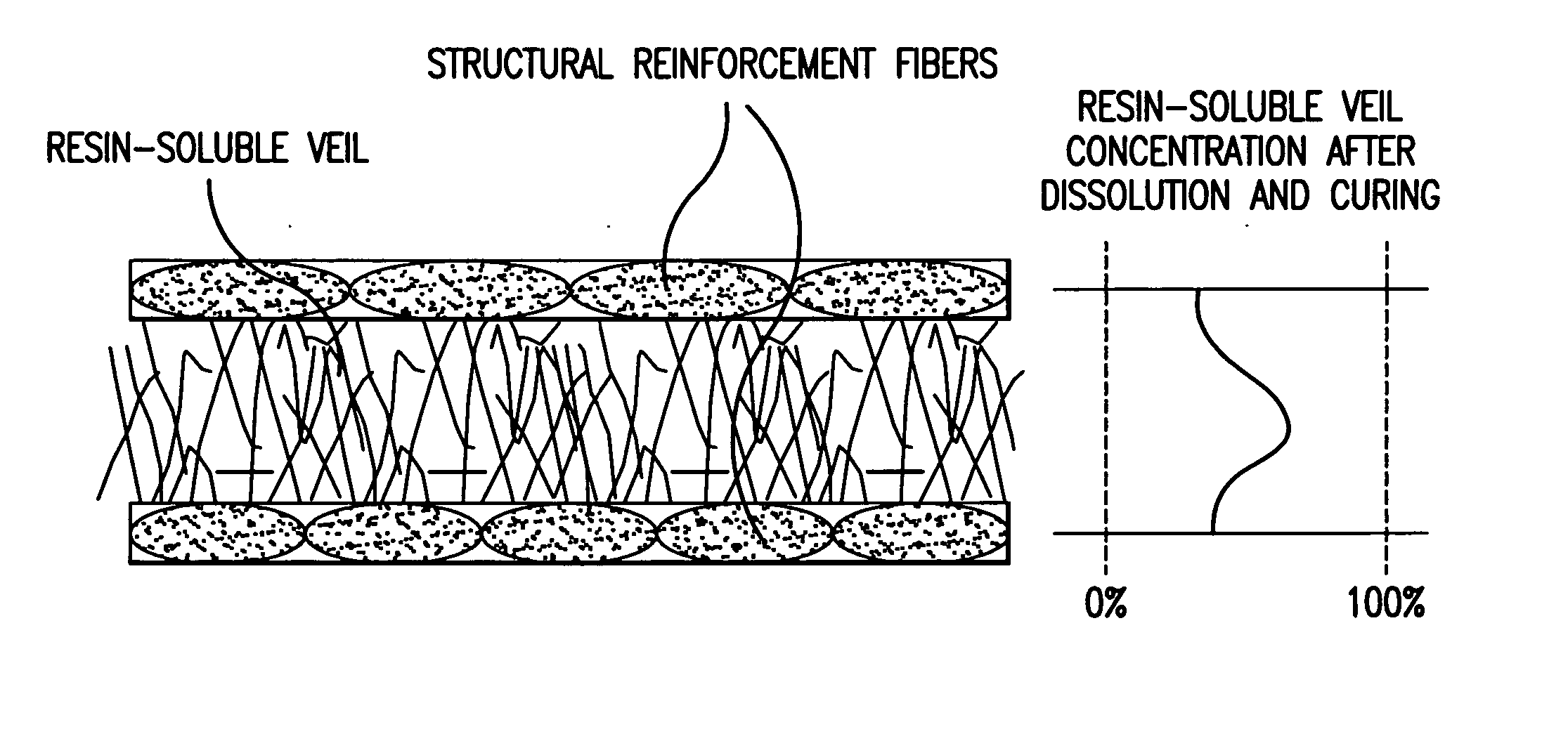
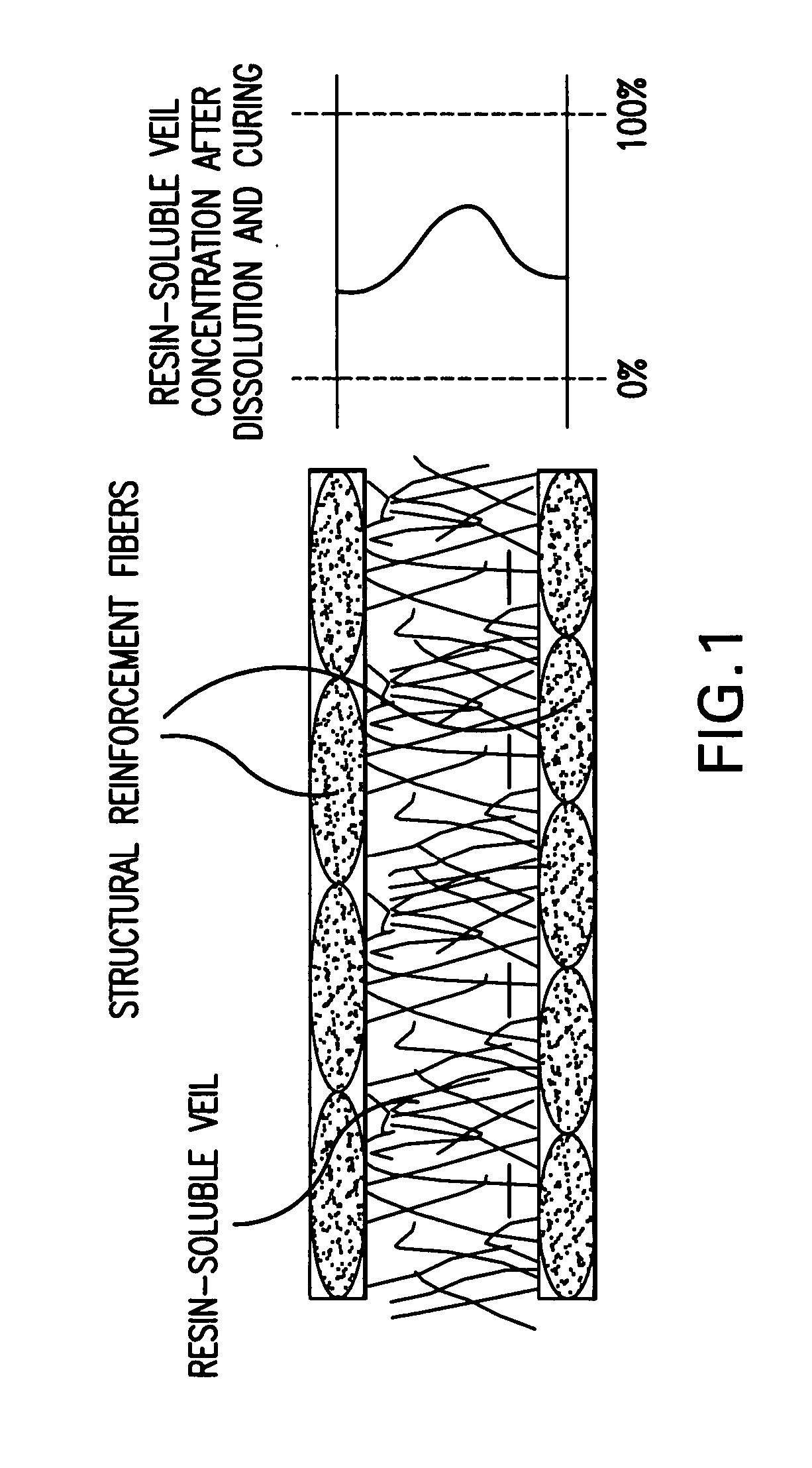
[0035] The present invention surprisingly overcomes the problems of prior prepreg and resin infusion systems. A preferred embodiment of the present invention comprises a non-woven veil of resin-soluble thermoplastic interposed between plies of dry structural reinforcement fiber for resin infusion to enhance inter-laminar toughness and other properties such as flame, smoke and toxicity (FST), and preforming capabilities.
[0039] Furthermore the permeable nature of the resin-soluble thermoplastic veil of the present invention provides more uniform flow and delivery of matrix resin throughout the preform than other thermoplastic films, which are not permeable.
[0040] Furthermore, the present invention utilizes thermoplastic polymers that are soluble within a resin system, thus allowing for more uniform distribution into the resin matrix than insoluble, meltable thermoplastics. Additionally, as the thermoplastic polymer of the present invention does not require high temperatures to melt in order to diffuse into the resin matrix, high processing temperatures are not required and out of autoclave manufacturing is possible.
[0044] A further aspect of the present invention is its ability to provide localized toughening of a composite. The present invention has the ability to lay up additional layers of thermoplastic toughening fabric in the areas requiring additional toughening.
[0045] A further aspect of the present invention is its ability to provide stabilization to a preform structure. A preferred embodiment interposes the resin-soluble thermoplastic veil between adjacent plies of, and in contacting relation to, structural reinforcement fibers in a preform; heating the preform sufficiently to soften the resin-soluble thermoplastic veil fibers in contact with the structural reinforcement fibers; allowing the thermoplastic fibers to at least partially adhere to the structural reinforcement fibers; and cooling the preform to solidify and harden the thermoplastic fibers to stabilize.
[0055] The present invention surprisingly finds that it is possible to provide elevated levels of a thermoplastic polymer adaptable to a resin infusion system, or the like by providing a part thereof as a resin-soluble thermoplastic polymer element in the form of a fiber, non-woven veil, mat, film, or the like capable of dissolving in a curable resin matrix, whereby it may be controllably combined in a curable resin matrix by means of at least partial phase transition as herein before defined to provide a polymer blend having desired properties.

Problems solved by technology

However, use of prepregs results in certain disadvantages including labor costs, difficulty in forming complex shaped parts, controlling toughened locations, and increased manufacturing costs due to the use of automated tape laying or fiber placement equipment and autoclaves for curing.
However, stitching and stapling for preform stabilization are typically limited as the preform cannot be shaped to conform to a complex structure's contour without disturbing the stitching or stapling.
However, this practice is limited in the amount of thermoplastic that can be added, requires high processing temperatures to ensure complete melting of the thermoplastic into the epoxy resin matrix.
While resin infusion technology is promising, composites which have high impact requirements usually contain thermoplastic toughening agents and it is difficult to add a thermoplastic toughening agent to an injectable resin because thermoplastic toughening agents possess such high molecular weight that they greatly increase the viscosity of the resin.
Therefore, only small amounts of a thermoplastic toughening agent can be added to the resin of these resin infusion systems.
These systems do not however attempt to introduce an additional resin matrix into the prepreg, as in resin infusion systems, and typically employ very high molecular weight thermoplastic polymers, which require excessively high temperature and pressure to melt.
While this method of co-weaving a thermoplastic fiber with the reinforcement fibers overcomes many of the problems of traditional resin infusion technology, it does not provide the capability of localized toughening.
Therefore, this method has limited flexibility in the amount of added thermoplastic polymer that may be incorporated into the composite part.
There is no provision in this co-weaving technology to concentrate additional amounts of thermoplastic polymer for increased toughening at a particular location of the composite part.
Moreover, the thermoplastic fibers are not practically able to be added to unidirectional tape due to the high tension required to manufacture unidirectional carbon fiber tape.
The incorporation of the thermoplastic toughening agent as a fiber co-woven into the structural reinforcement fiber further led to some difficulties in controlling amount of thermoplastic toughening agent in the resin.
The co-weaving method also results in increased manufacturing costs due to the requirement of spinning the thermoplastic polymer into a fiber capable of being woven with the structural reinforcement fibers.
Moreover, the added complexity of co-weaving a dissimilar material such as a thermoplastic fiber with the structural reinforcement fibers increased manufacturing costs.
Additionally, co-weaving of the thermoplastic fiber disturbed the arrangement and straightness of the structural reinforcement fibers, thus reducing in-plane mechanical properties and did not afford the interlaminar toughening that was desired of composite systems.
See U.S. Pat. Nos. 6,437,080B1, 5,288,547, EP 1 473,132 A2 and EP 0327,142 A. However, this interleaf toughening material does not dissolve into the resin, but rather melts at the higher temperatures attained during cure providing limited diffusion and requiring higher temperatures and cure times to advance the melting and diffusion.
Melting interleaf layers are limited in that it is difficult to manufacture quality components by RIFT or VARTM, out of the autoclave, without the benefit of high temperatures and cure times needed to advance the melting and diffusion in these systems.
Curing with vacuum only or with no pressure causes the components to have very high void content thus, leading to poor mechanical properties.
Melting interleaf systems are further limited in that the lack of uniform and complete dissolution creates interfaces between the resin and reinforcement fibers.
This interface can in turn decrease composite resistance to fluids and cause a reduction in hot / wet mechanical properties.
Furthermore, the lack of complete dissolution of the thermoplastic and the resin means that no synergy between the properties of the two chemical species can be obtained; for example the resin will maintain its brittleness and the thermoplastic will remain sensitive to solvents.
However, melting and diffusion of these thermoplastics into the resin matrix also requires the high temperature curing processes and is limited in the amount and extent of diffusion of the thermoplastic.
Another disadvantage of particle toughening is that during resin infusion, the particles can be washed away by the resin flow and can uncontrollably agglomerate at undesirable locations.
This causes the mechanical properties of the composites to be not uniform and may cause undesirable voidage and porosity due to varying viscosities of the resin causing a non-homogeneous flow front.
However, localized toughening of composites remains difficult using these techniques during manufacture because the toughening agent is uniformly coated onto the reinforcement fibers and cannot be controllably increased in any particular area of the part that may require increased toughness.
Nevertheless dispersion is typically poor due to difficulty in controlling distribution of particles and uniformity of particle size which can influence rate and degree of melting, and the barrier effect of a continuous film during resin infusion.
Specifically, the need for an improved means of incorporating and controlling the amount of thermoplastic toughener in a resin infusion system remains unsatisfied.

Method used


Image

  • Resin-soluble thermoplastic veil for composite materials
  • Resin-soluble thermoplastic veil for composite materials
  • Resin-soluble thermoplastic veil for composite materials

Examples


example 1

Veil Manufacturing

[0189] 54 tex fibers made from a PES polymer are chopped to an average fiber length of 8 mm using a rotary blade chopper. The chopped fibers are then dispersed by hand on a release film and pressed between a press hot platens at 180° C. for 1 hour with a 15 bar piston pressure. The platens are then cooled down to 60° C. and the resulting product is extracted. The product has a dimension of 15×15″ and an AW of 60 gsm. The veil is stable and handleable for processing purposes during manufacture.

example 2

Veil Dissolution

[0190] A sample of veil made in the previous example (AW=60 gsm) weighing 10 grams is combined with 30 g of Cycom™ 977 20 resin by dipping the veil into the resin. The veil / resin combination is then placed in an oven at 130° C. for 1 hour. The resulting product is then observed under a microscope. The microscopic observation shows a homogeneous solution without visible traces of undissolved fibers or high concentration of thermoplastic.

example 3

Composite Manufacturing

[0191] Layers of a HTA-6K-370 GSM 5HS carbon fabric were interleafed with non-woven fabrics to manufacture RTM panels with a Vf=55% and a target thermoplastic content of 25% wt in the resin (54 gsm in the fabric). FIG. 4 illustrates this resin infusion process while FIG. 5 illustrates the veil and reinforcement fiber orientation.

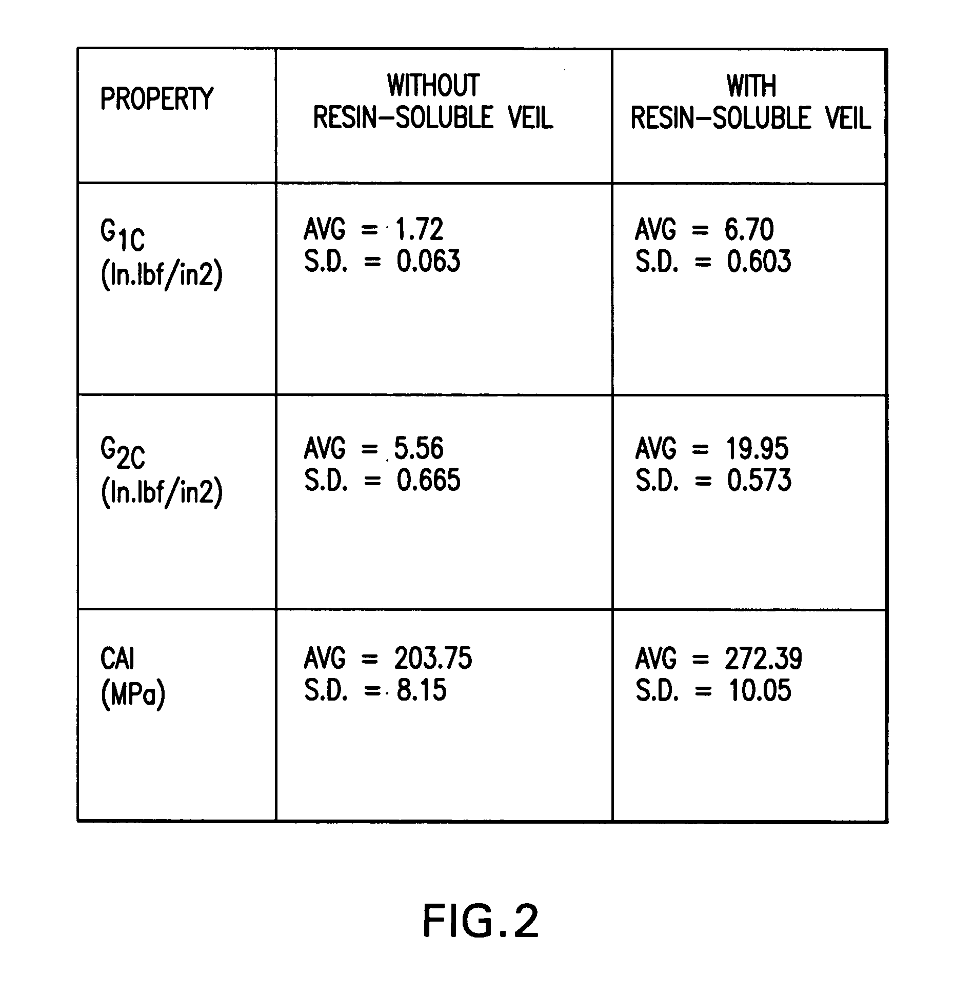
[0192] The results show that the insertion of the non-woven veil provides compression after impact (CAI) testing numbers equivalent to traditional toughened prepreg systems using the non-woven resin-soluble veil. The key mechanical properties were tested and the results are reported in Table 1 below:

TABLE 1


PUM

PropertyMeasurementUnit
Temperatureaaaaaaaaaa
Weightaaaaaaaaaa
Solubility (mass)aaaaaaaaaa

Abstract

A resin-soluble thermoplastic polymer veil toughening element for a curable composition wherein the polymer element is a non-woven veil in solid phase adapted to undergo at least partial phase transition to fluid phase on contact with a component of the curable resin matrix composition in which it is soluble at a temperature which is less than the temperature for substantial onset of gelling and / or curing of the curable composition and which temperature is less than the polymer elements melt temperature; a method for the preparation thereof, a preform support structure for a curable composition comprising the at least one thermoplastic veil element together with structural reinforcement fibers, methods for preparation thereof, a curable composition comprising the at least one thermoplastic veil element or the support structure and a curable resin matrix composition, a method for preparation and curing thereof, and a cured composite or resin body obtained thereby, and known and novel uses thereof.

Description

BACKGROUND OF THE INVENTION [0001] 1. Field of the Invention [0002] This invention relates to the manufacture and use of non-woven thermoplastic veils for use in complex and diverse high performance composite applications. In preferred embodiments, this invention relates to a resin-soluble thermoplastic polymer formed into a non-woven veil fabric or random mat for incorporation into high performance composite manufacturing applications to aid part manufacturing and improve desired properties. [0003] 2. Description of the Related Art [0004] Fiber-reinforced resin matrix composites are widely accepted for use as high strength low weight engineering materials to replace metals in aircraft structural applications and the like. These curable compositions may be made by laminating prepregs comprising high strength fibers, such as glass, quartz, graphite (carbon), boron, aramid or the like impregnated with an epoxy resin matrix. Important properties of such composites are high strength and...

Claims


Application Information

Patent Timeline
IPC IPC(8): D04H13/00
CPCB32B5/022D04H13/006B32B5/26B32B7/10B32B2250/20B32B2260/023B32B2262/0207B32B2262/0215B32B2307/54B32B2307/558B32B2307/718B32B2307/7242B32B2307/7265B32B2605/18C08J5/046B32B5/08Y10T428/249933Y10T428/249934Y10T428/249939Y10T428/24994Y10T428/249942Y10T428/249947Y10T428/249949Y10T428/24995Y10T428/249952Y10T442/198Y10T442/20Y10T442/2033Y10T442/30Y10T442/3569Y10T442/3707Y10T442/3715Y10T442/3789Y10T442/637Y10T442/68B32B2262/02
Inventor LOFARO, CARMELOABUSAFIEH, ABDELWEBB, WILLIAM ERWINDOYLE, MARC
Owner CYTEC TECH CORP
Learn More