

Top coating composition for photoresist and method of forming photoresist pattern using the same
- Summary
- Abstract
- Description
- Claims
- Application Information
AI Technical Summary
Benefits of technology
Problems solved by technology
Method used
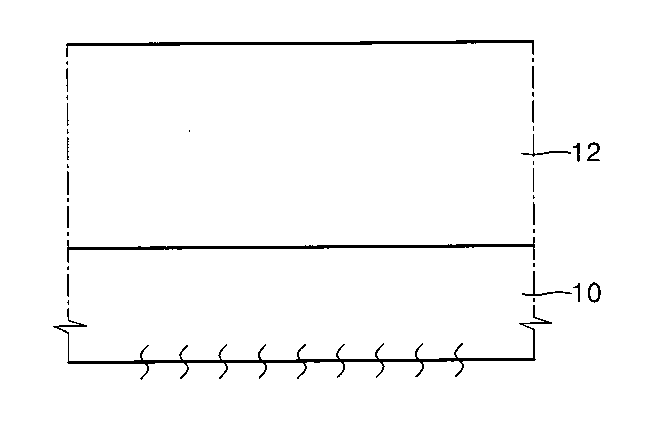
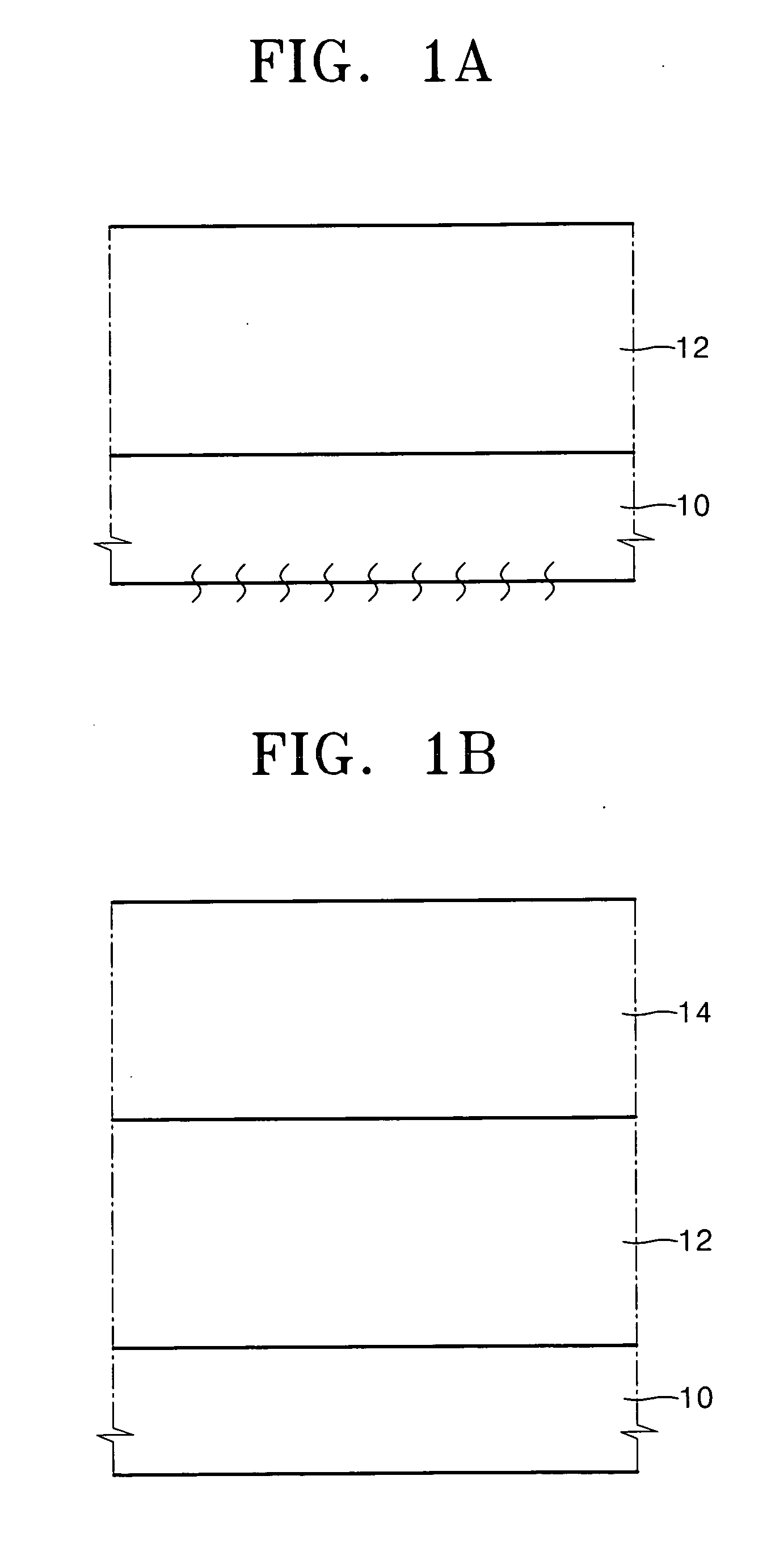
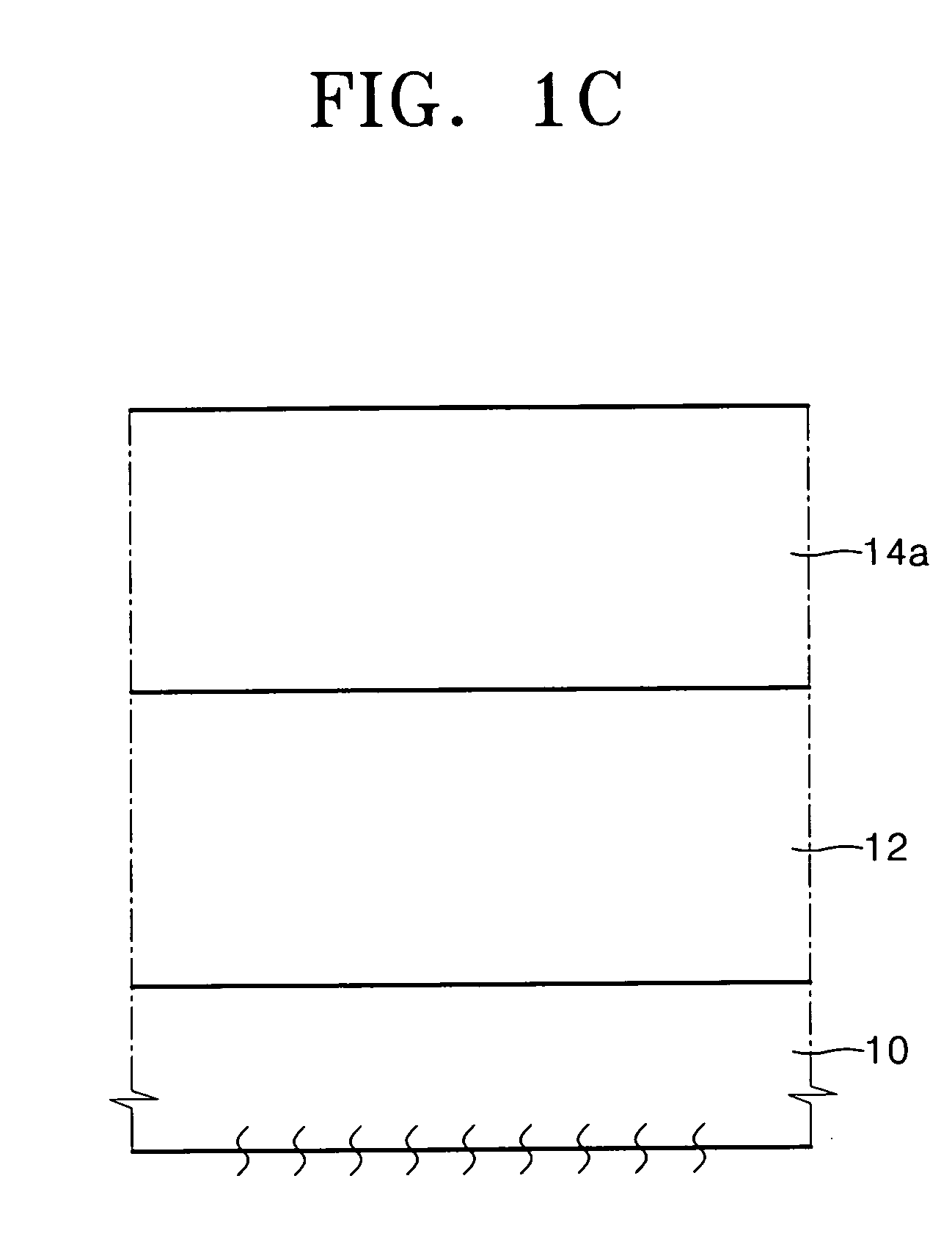
Image

Examples
example 1
EXAMPLE 1-1
Barrier Characteristics of Top Coating Layer with Respect to Deionized Water
[0079] A methoxy-2-propanol solution, in which an 1% by weight of poly(2-ethyl-2-adamantyl acrylate-co-3-hydroxypropyl acrylate) obtained by mixing and polymerizing 2-ethyl-2-adamantyl acrylate and 3-hydroxypropyl acrylate with a mole ratio of 3:9 was dissolved, was spin-coated onto an 8-inch bare-silicon wafer, and was heat-treated at about 100° C. for about 60 seconds to form a top coating layer. Then, the wafer on which the top coating layer was formed was rinsed with deionized water for about 90 seconds. At this time, the dissolution rate of the top coating layer was about 0.322 Å / sec. The wafer was developed with a 2.38% by weight of a tetramethylammonium hydroxide solution. As a result, the top coating layer was partially removed.
example 1-2
Barrier Characteristics in Immersion Lithography Process using Top Coating Layer
[0080] A photoresist pattern was formed using an immersion lithography process and a top coating layer including a top coating composition according to an embodiment of the present invention. Barrier characteristics of the top coating layer were measured. In this case, during the exposure, mimic immersion lithography was performed instead of exposure via a liquid medium. That is, the subject to be exposed was immersed in deionized water for 60 seconds, dry-exposed, and then immersed in deionized water for 60 seconds. Hereinafter, the process conditions of the mimic immersion lithography of the current example are equally applied to other examples unless other specific conditions therefor are provided.
[0081] An anti-reflective coating (ARC) material (ARC 26A™ manufactured by Nissan Chemical Industry) used for an exposure wavelength of 193 nm was spin-coated on an 8-inch bare silicon wafer, and then bake...
example 2
EXAMPLE 2-1
Barrier Characteristics of Top Coating Layer with Respect to Deionized Water
[0083] An n-butanol solution, in which an 1% by weight of poly(2-ethyl-2-adamantyl acrylate-co-acrylic acid-co-3-hydroxypropyl acrylate) obtained by mixing and polymerizing 2-ethyl-2-adamantyl acrylate, acrylic acid, and 3-hydroxypropyl acrylate with a mole ratio of 4:1:9 was dissolved, was spin-coated onto an 8-inch bare-silicon wafer, and was heat-treated at about 100° C. for about 60 seconds to form a top coating layer. Then, the wafer on which the top coating layer was formed was rinsed with deionized water for about 90 seconds. At this time, the dissolution rate of the top coating layer was about 0.098 Å / sec. The wafer was developed with a 2.38% by weight of a tetramethylammonium hydroxide solution. As a result, the top coating layer was completely removed.
PUM
| Property | Measurement | Unit |
|---|---|---|
| Mw | aaaaa | aaaaa |
| temperature | aaaaa | aaaaa |
| Mw | aaaaa | aaaaa |
Abstract
Description
Claims
Application Information