
Method and apparatus for producing charcoal

a technology of charcoal and methods, applied in the direction of lighting and heating apparatus, combustion types, furniture, etc., can solve the problems of large amount of fuel consumed, high energy demand of applications, proportionately higher volume of charcoal, etc., and achieve the effect of reducing the unit cost of producing charcoal and producing higher units of charcoal yield

Inactive Publication Date: 2006-12-14
NUCOR CORP
View PDF2 Cites 22 Cited by
  • Summary
  • Abstract
  • Description
  • Claims
  • Application Information

AI Technical Summary

Benefits of technology

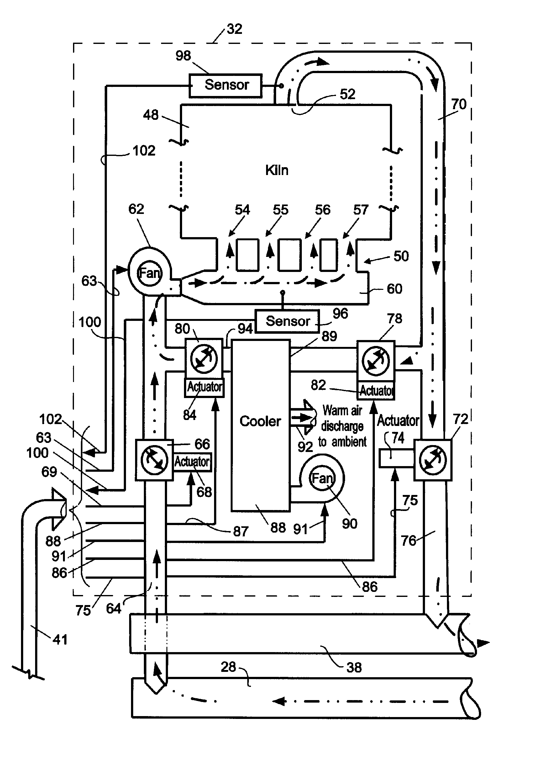
[0011] One object of the present invention is to provide a method and apparatus for producing higher units of charcoal yield per unit of time. Another object of the present invention is to a method and apparatus which reduces the unit cost of producing charcoal for use in industrial applications. Still another object of the present invention is to provide a method and apparatus capable of producing charcoal with minimal discharge of the toxic constituents of the production process into the environment.
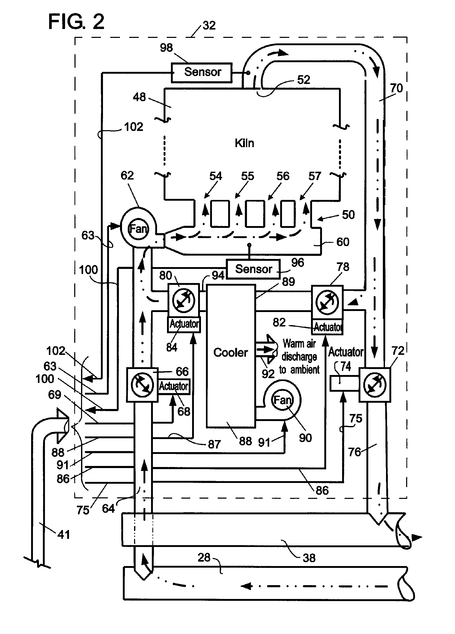
[0012] According to one aspect of the present invention, charcoal is produced in batch process cycles having an endothermic or drying phase, an exothermic or pyrolysis phase, and a cooling phase, and which is performed concurrently in each of a plurality of kilns (or retorts); each kiln being supplied with a woody raw material charge which is subjected to forced hot process gas and cooled process gas convection within the kiln to reduce the interval times of the endothermic and cooling phases, thereby reducing the overall production cycle time. In further accord with this aspect of the invention, the forced hot process gas and cooled process gas convection of the charge within each kiln is provided by one or more gas handlers associated with the kiln.
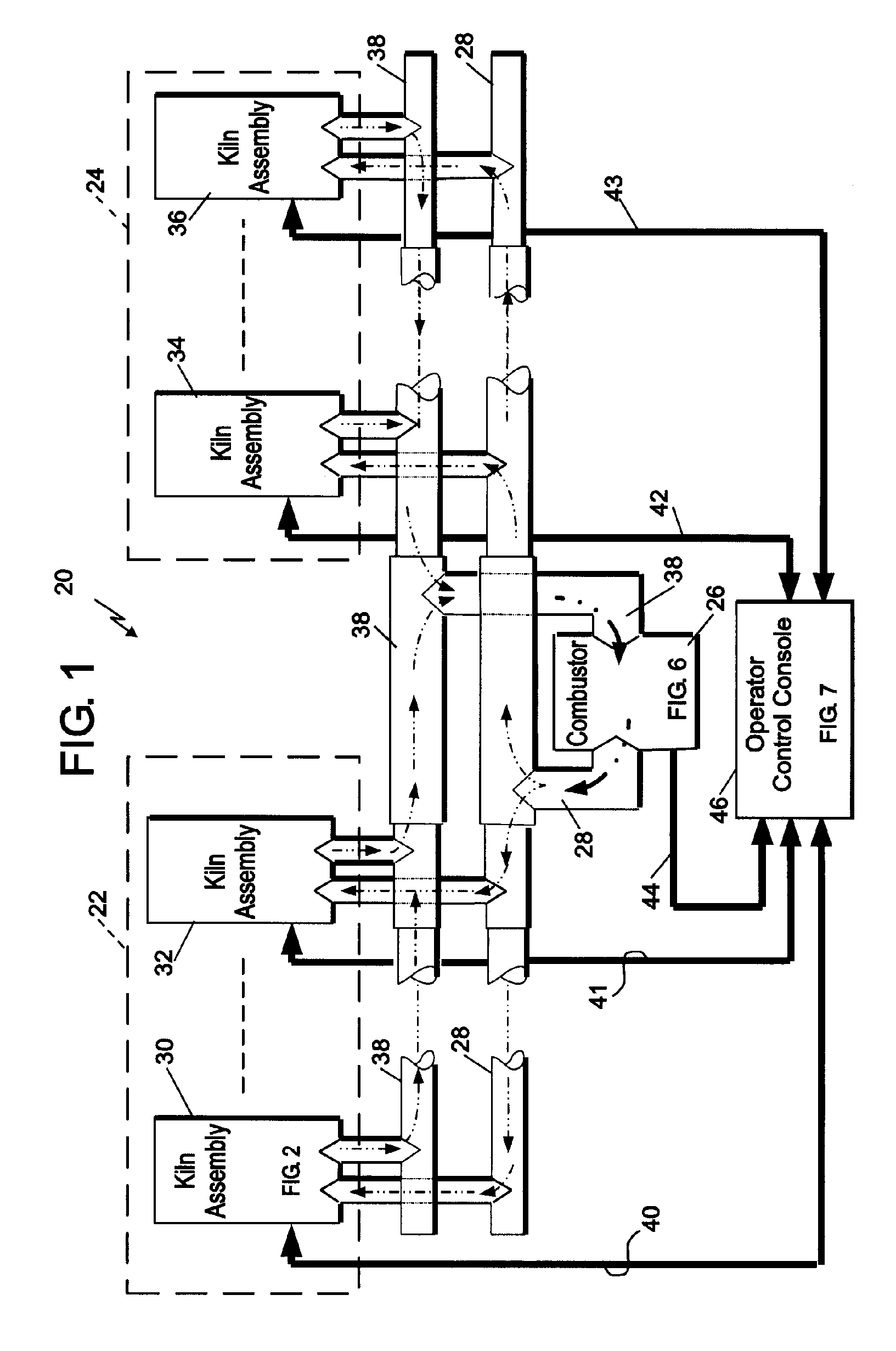
[0013] According to another aspect of the invention the kilns are supplied with heating hot process gas from an external combustor during the endothermic phase, the hot process gas being recirculated between the combustor and each kiln through enclosed supply and return ducts, thereby reducing sacrificial consumption of the charge itself and increasing charcoal yield. In further accord with this aspect of the invention, the pyrolysis phase off-gases discharged from the kilns are returned to the combustor and consumed as fuel to produce the combusted hot process gas, whereby the hot process gas supplied to the kilns are essentially free of volatile organic compounds (VOC) and the opportunity for discharge of VOC s to the atmosphere are minimized. In still further accord with this aspect of the invention, the batch processes performed in the kilns are performed in an ordered sequence in which a balance may be achieved between the collective volume of pyrolysis phase discharged gases flowing through the return duct is sufficient to fuel the combustor as necessary to provide the heating load demand of the kilns that are in the endothermic phase, thereby achieving system equilibrium.
[0014] The present invention significantly reduces the cycle time necessary to produce charcoal, thereby allowing for a higher volume of charcoal per unit time, as necessary to satisfy the scheduled fuel demands of industrial applications. The use of an external combustor minimizes sacrificial consumption of the woody material charge during pyrolysis so as to produce a higher charcoal per unit of raw material yield. In addition, the hot process gas supply ducts and the kiln subassembly are oxygen free, and the positive pressure within the supply and return ducts flush the combustible VOC gases from the kiln, further minimizing opportunity for combustion within the kiln. All of which produces both a higher ratio yield of charcoal to raw charge and a higher overall volume charcoal per unit time to ensure a lower unit cost of production over the prior art methods and apparatus.

Problems solved by technology

These type of industrial applications have a high energy demand and consume large quantities of fuel.
Since charcoal does not have the heat content of coke its use in these applications consumes a proportionately higher volume of charcoal.
Control of emissions from batch kilns is difficult because the process and emissions are cyclic, with the emission composition and flow rate changing over the process cycle.

Method used


Image

  • Method and apparatus for producing charcoal
  • Method and apparatus for producing charcoal
  • Method and apparatus for producing charcoal

Examples


Embodiment Construction

[0029] The present invention is to a method and apparatus for producing charcoal in a high volume batch process. The process is performed in individual kilns which share a common external combustor, and whose primary source of fuel are the VOC wood gases produced by the exothermic, or pyrolysis phase of each kiln's batch cycle. In the best mode embodiment the kilns perform their processes in a relative ordered sequence intended to provide a continuing supply of wood gases to satisfy the endothermic phase heat demand of the kilns with the pyrolysis wood gases produced by those kilns in their exothermic phase. This provides a system energy balance and minimizes the need for supplementary fuels.

[0030] While the number of kilns in a given system configuration is principally a function of the production demand and throughput (batch process volume) placed in the system, which can be scaled within limits, the invention's best mode embodiment limits the minimum and maximum number of kilns ...


PUM

PropertyMeasurementUnit
temperatureaaaaaaaaaa
timeaaaaaaaaaa

Abstract

Apparatus for batch processing source material into charcoal in a battery of kilns, each of which use forced convection of process gases through the source material to shorten the process cycle time, and all of which use an external combustor to burn the process waste gases from each kiln to provide the primary source of applied energy for the process.

Description

COPYRIGHT [0001] The contents of this document are subject to copyright protection. The copyright owner maintains all rights in copyright to these contents but has no objection to their reproduction in the form published by the United States Patent and Trademark Office. TECHNICAL FIELD [0002] This invention relates to a method and apparatus for the manufacture of charcoal, and more particularly to the large scale production of charcoal for industrial fuel applications. BACKGROUND ART [0003] As known, charcoal is the solid carbon residue resulting from pyrolysis of carbonaceous materials having a cellulosic fiber structure. These include woody materials and vegetable biomass, such as tree stock, tree bark, twigs, sawdust, and even nut shells, as well as processed materials, such as corrugated paper board and paper. Depending on whether the produced charcoal is a commercial product or the byproduct of solid waste disposal, its intended use determines the type of carbonaceous material ...

Claims


Application Information

Patent Timeline
Patent Type & Authority Applications(United States)
IPC IPC(8): C01B31/02C01B31/00
CPCC01B31/02Y02E50/14C10B53/02C10B49/02C01B32/05Y02E50/10
Inventor TEETER, GERALD A.KAUFMAN, JARED S.PRESSLY, JOHN L.GOEBEL, CHRISTOPHER ADAMDEBSKI, PAUL DAVID
Owner NUCOR CORP
Learn More