

Aromatic amine derivatives and electroluminescence device using the same
a technology of aromatic amine and derivatives, applied in the field of organic electroluminescence, can solve problems such as achieving practical performance, and achieve the effect of prolonging the life and improving the efficiency of light emission
- Summary
- Abstract
- Description
- Claims
- Application Information
AI Technical Summary
Benefits of technology
Problems solved by technology
Method used
Image

Examples
example
(A) Synthesis Example 1
Synthesis of Intermediate Product
(A-1) Synthesis of 2,7-dibromo-9,10-dihydrophenanthrene
[0188] Dissolving 30.0 g of 9,10-dihydrophenanthrene into 200 milliliter of (MeO)3PO, and a solution prepared by mixing 56.7 g of bromine with 100 milliliter of (MeO)3PO was dripped into the resultant solution contained in a flask. Shading the flask from light, the reacted solution was stirred for 8 hours. As a result, a white precipitation generated. After the completion of the reaction, the white precipitation in the reacted solution was separated by filtration. After washing the resultant crystal with a use of methanol, it was vacuum dried and 32.7 g of 2,7-dibromo-9,10-dihydrophenanthrene was obtained as white crystal.
(A-2) Synthesis of 2,7-dibromophenanthrene
[0189] Preparing 32.7 g of 2,7-dibromo-9,10-dihydrophenanthrene, 24.1 g of 2,3-dichloro-5,6-dicyanobenzoquinone (DDQ) and 500 milliliter of benzene as a mixture solution, the solution was refluxed with heating...
synthesis example 2
(B) Synthesis Example 2
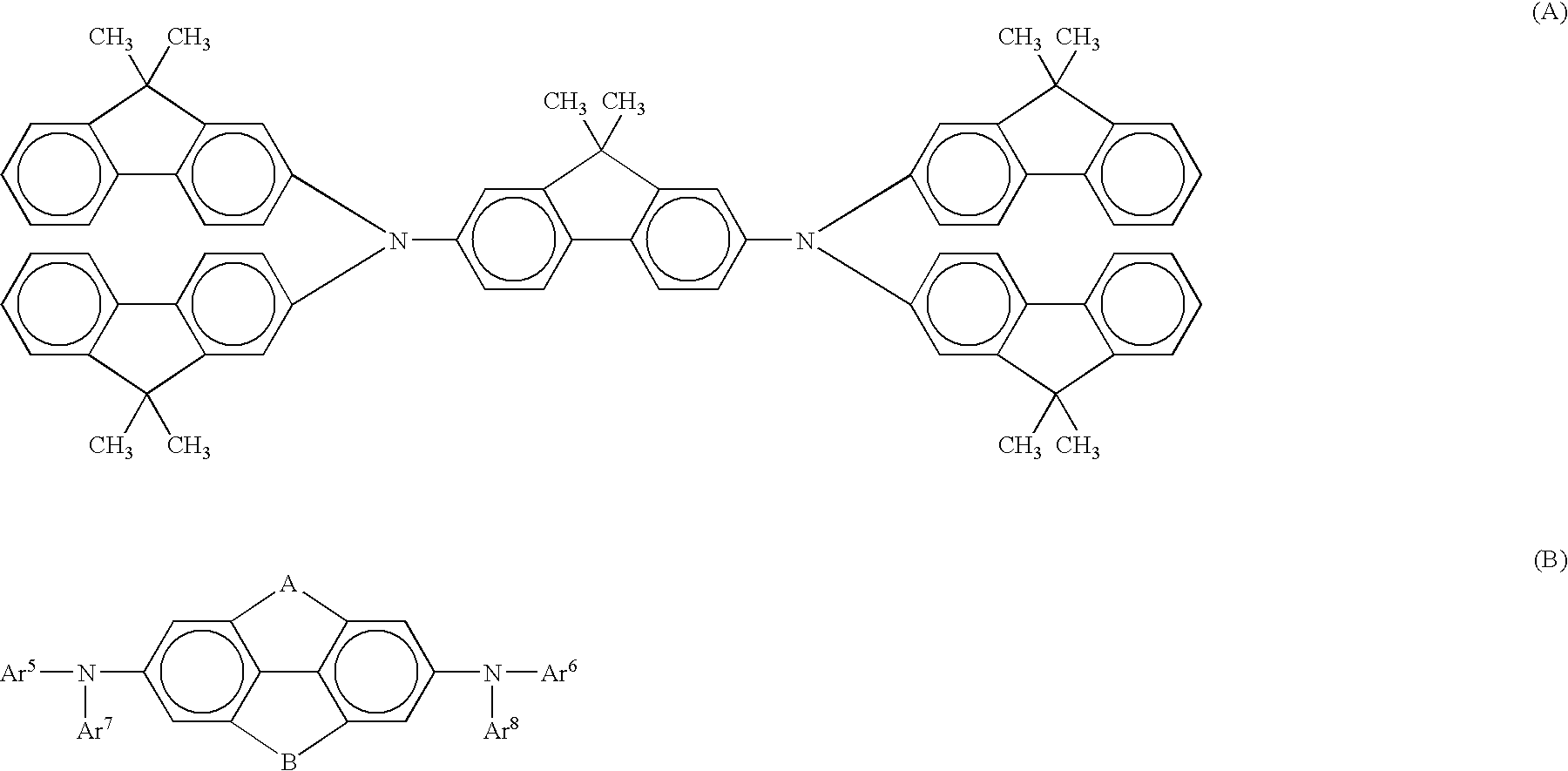
Synthesis of Phenanthreneamine Derivative
[0190]
(B-1) Synthesis of Compound 1
[0191] Adding 0.66% by weight toluene solution in an amount of 100 microliter prepared by dissolving tri-t-butylphosphine into a mixed solution prepared by dissolving 3.36 g of 2,7-dibromophenanthrene, 5.26 g of N-phenyl-1-naphthylamine, 183 milligram of tris(dibenzylideneacetone)dipalladium (O) and 1.34 g of t-butoxysodium into toluene in an amount of 100 milliliter, the resultant solution was refluxed with heating for 5 hours. After cooling the resultant solution down to a room temperature, the precipitated solid was separated by filtration. The resultant solid was washed with uses of methanol, water, methanol and toluene sequentially and further, it was dried under a reduced pressure. After dissolving the solid in hot toluene, it was filtered while heating and then, cooling down to a room temperature, a crystal resultantly precipitated. The crystal was separated by filtration and ...
example 1
[0212] A glass substrate (manufactured by GEOMATEC Company) of 25 mm×75 mm×1.1 mm thickness having an ITO transparent electrode was cleaned by application of ultrasonic wave in isopropyl alcohol for 5 minutes and then by exposure to ozone generated by ultraviolet light for 30 minutes. The glass substrate having the transparent electrode lines which had been cleaned was attached to a substrate holder of a vacuum vapor deposition apparatus. On the surface of the cleaned substrate at the side having the transparent electrode, a film of Compound 1 having a thickness of 80 nanometers was formed in accordance with a resistance heating vapor deposition process so that the formed film covered the transparent electrode. The formed film of Compound 1 worked as the hole injecting layer. Over the formed film of Compound 1, 9-(2-naphthyl)-10-[4-(1-naphthyl)phenyl]anthracene (abbreviated as AN-1 below) having a thickness of 40 nanometers was further formed in accordance with the resistance heatin...
PUM
| Property | Measurement | Unit |
|---|---|---|
| Percent by mass | aaaaa | aaaaa |
| Time | aaaaa | aaaaa |
| Time | aaaaa | aaaaa |
Abstract
Description
Claims
Application Information