
Electrostatic latent image developer and image-forming apparatus

Inactive Publication Date: 2007-03-01
FUJIFILM BUSINESS INNOVATION CORP
View PDF12 Cites 16 Cited by
  • Summary
  • Abstract
  • Description
  • Claims
  • Application Information

AI Technical Summary

Benefits of technology

[0052] For the aforementioned reason, in order to exhibit the effect of the invention, a spray method, which can provide a uniform coating, is preferably used to form an inner layer, whereas an immersion method is preferably used to form an outermost layer. Specifically, carrier cores having thereon a coating which contains an electrically conductive material such as carbon black and is obtained by spray coating under stirring stress are put into the coating solution to form an outermost layer, and the resultant overcoat is cross-linked. Thereby, a resin coating layer which is uniform to a certain extent can be obtained and, further, the electrically conductive material can be suppressed from separating from the carrier cores in a printer. The reason for this is that the cross-linked hard outermost layer covers the inner layer including more electrically conductive material.
[0053] The solvent used in the solution for forming a coating resin layer needs to dissolve a coating resin (matrix resin) and otherwise it is not particularly limited. Examples of the solvent include aromatic hydrocarbon solvents such as toluene and xylene, ketones such as acetone and methyl ethyl ketone, and ethers such as tetrahydrofuran and dioxane. A sand mill, a dyno mill and / or a homomixer may be used for dispersing the resin particles and the electrically conductive power.
[0054] The solution for forming a coating resin layer may contain a charge control agent and a resistance control agent, if necessary. When a silicone resin is used as a coating resin, the solution preferably contains a metal catalyst to help cure the resin. An organic compound including aluminum, calcium, barium, manganese, tin, cobalt and / or zinc is known as the metal catalyst.
[0055] Either an external heating method or an internal heating method may be used for baking the resin coated on the cores. For example, the resin may be baked with a stationary-type or fluid-type electric furnace, a rotary electric furnace, a burner furnace or microwave. The baking temperature depends on the type of the resin used, but needs to be equal to or more than the melting point or glass transition point of the resin. Moreover, when a thermosetting resin or a condensation cross-linkable resin is used, it is necessary to raise the temperature of the resin so as to sufficiently advance curing of the resin. In the case of, for example, a silicone resin, the resin is preferably kept at a temperature of about 200 to about 300° C. for about 30 minutes.
[0056] After the resin coated on the surface of each of the core particles is baked, the resultant is cooled and disintegrated, and the particles obtained are classified to gain carrier particles having a controlled average diameter and a cross-linked coating resin layer. The particles obtained by the disintegrating may be subjected to a post treatment so as to remove roughness and / or flash on the surfaces thereof and to sufficiently disintegrate agglomerate particles arising through the coating. Any of post treatment methods or apparatuses known in the art may be used so long as mechanical stress can be applied to the particles. For example, the post treatment apparatus can be a Nauter mixer, a ball mill and / or a vibro mill, but is not restricted thereto.
[0057] A method for fixing resin particles on the surfaces of carrier cores in a dry manner is known as one of conventional coating methods. However, good carrier particles which can prevent an electrically conductive material such as carbon black from separating from the core particles cannot be obtained by this method, since the carrier cores cannot be coated sufficiently and uniformly.

Problems solved by technology

However, the surface coating layer abrades during a continuous operation of the high-speed printer, and staining of color toners by carbon black becomes evident as a result of the continuous operation, though no separation of carbon black is observed at the start of the operation.
On the other hand, as for fixing systems, the most crucial issue in the high-speed printer is to prevent paper from jamming and paper powder from occurring by friction between the printer and paper sheet.
Moreover, it is a crucial issue to stabilize characteristics of the developer in the ultra-high speed, on-demand printer.

Method used


Image

  • Electrostatic latent image developer and image-forming apparatus
  • Electrostatic latent image developer and image-forming apparatus
  • Electrostatic latent image developer and image-forming apparatus

Examples


examples

[0151] The invention will be described in detail with reference to examples. In the following descriptions, “part(s)” and “%” respectively denote “part(s) by mass” and “% by mass”, unless otherwise specified.

Carrier 1

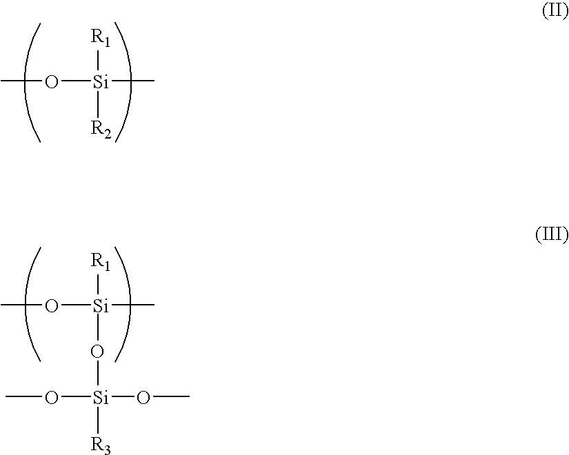
[0152] An amount of a cross-linkable silicone resin (manufactured by Shin-Etsu Chemical Co., Ltd.) having trifluoropropyl groups in a content of 15%, which amount corresponds to 200 parts of the solid matter of the silicone resin, is taken. The silicone resin is dissolved in 1000 cc of toluene serving as a solvent. Electrically conductive carbon black (KETCHEN BLACK EC600JD manufactured by Lion Co., and having a BET specific surface area of 1270 m2 / g) is added to the resultant solution so that the mass ratio of the carbon black to the solid matter of the solution is 15%. Two parts of an organic curing catalyst, aluminum di-n-butoxide monoethylacetoacetate, is added to the resultant mixture, and the resultant blend is stirred with a pearl mill to obtain a coating liqu...

example 21

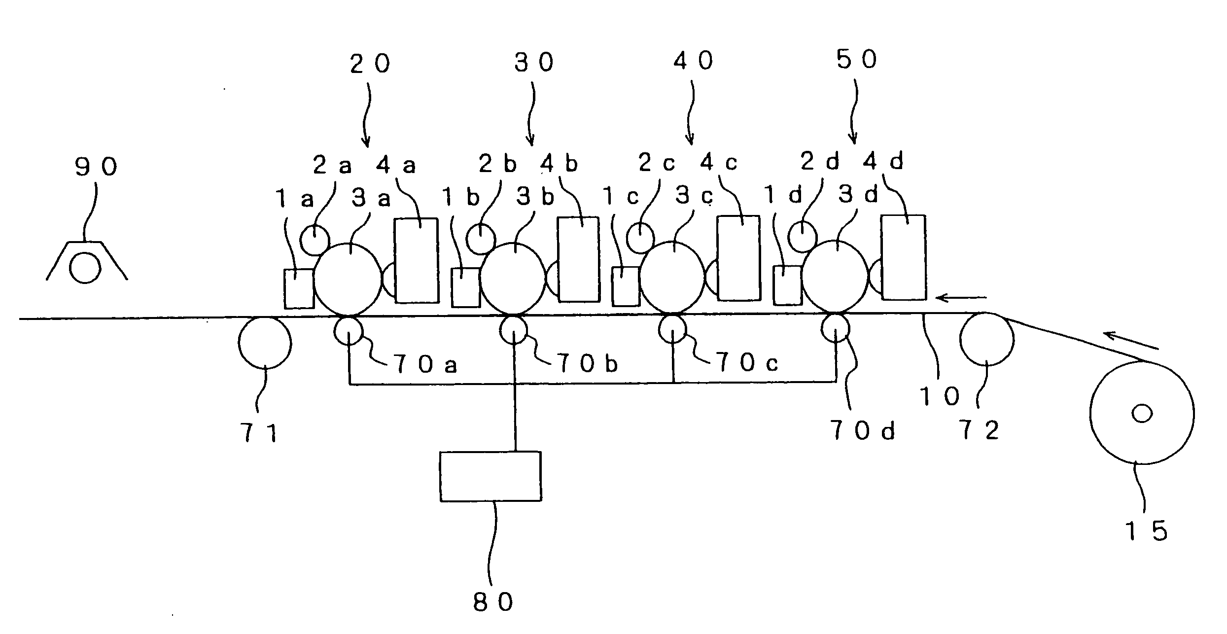
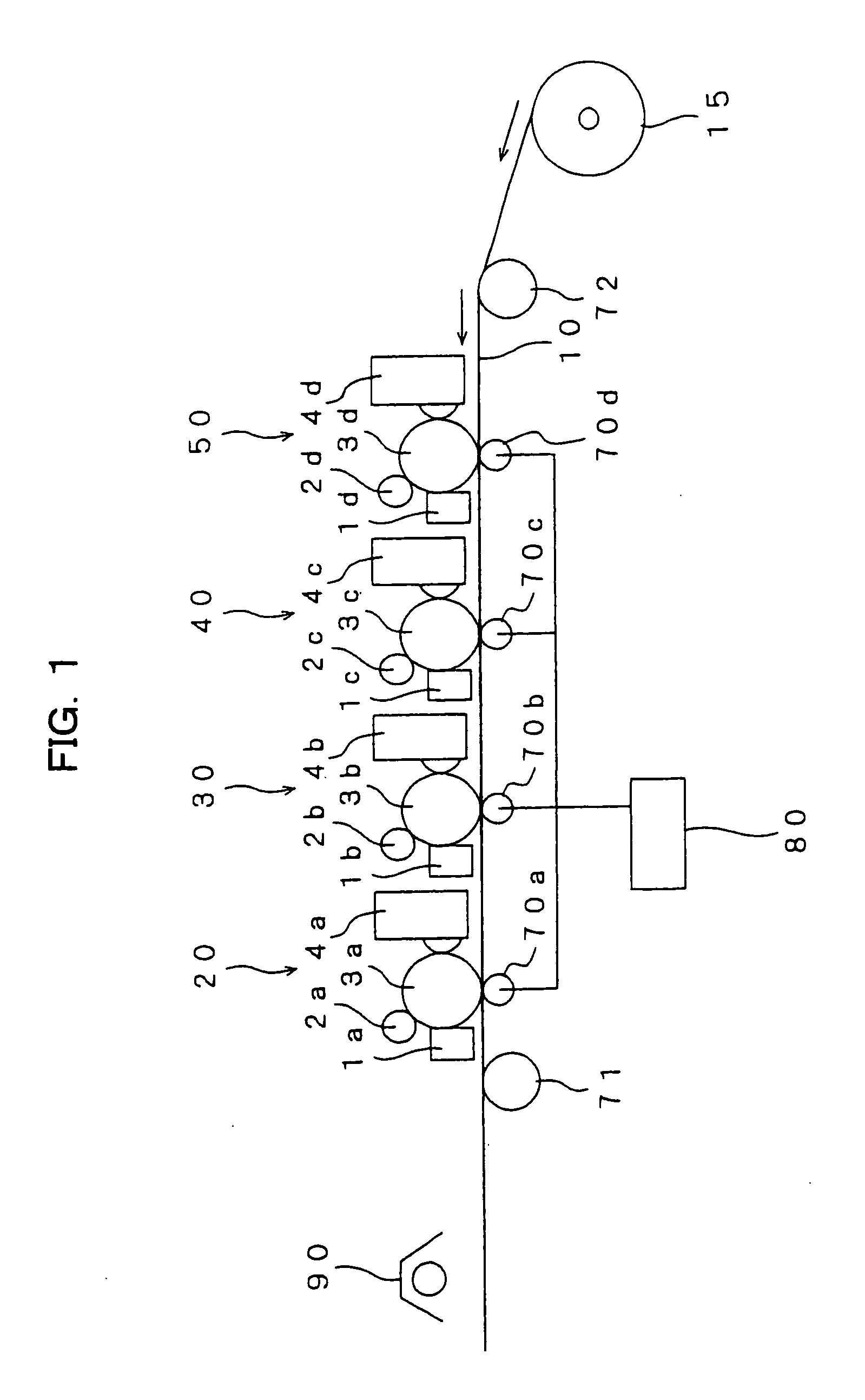
[0202] A tandem printer shown in FIG. 1, and having four developing units in a row, an ability of outputting 400 A4-size sheets of paper for one minute and a linear velocity of 2000 mm / sec is provided by remodeling printers, DOCUPRINT 1100CF manufactured by Fuji Xerox Co., Ltd. The developers including the carrier 1 and the respective yellow, magenta, cyan and black toners are put in the four developing units, respectively. The yellow toner used is YT-3. An image is continuously printed on one million sheets of paper and the characteristics of the printed images are evaluated in the above-described manner.

[0203] The results show that, even when an image is printed on one million sheets of paper, printed images whose lightness, toner amount and fixing rate hardly change can be obtained.

example 22

[0204] The developer including the invisible toner (ST-1) serving as a toner for cipher printing and the carrier 1 is put in a printer obtained by remodeling a printer, DOCUPRINT 1100CF manufactured by Fuji Xerox Co., Ltd., and having an ability of outputting 400 A4-size sheets of paper for one minute. An image (bar code image) is continuously printed on one million sheets of paper with the printer. The quality of the last printed image is almost the same as that of the first printed image.

[0205] Readability of the bar code image printed on the 1,000,000th sheet of paper is judged. The bar cord reader used in the judgment is obtained by remodeling a bar code printer, THLS-6000 & TBR-6000 manufactured by Token Co., and having, as a light source, a laser which emits light having a wavelength of 780 nm, and a detector. In the remodeling, the light source is replaced with an IR light emission diode (GL480Q manufactured by Sharp Co., and having a peak emission wavelength of 950 nm) and ...


PUM


Abstract

The invention discloses an electrostatic latent image developer including a toner and a carrier. The carrier has cores and a coating resin including an electrically conductive material on the surface of each of the cores. The coating resin has an inner portion and an outermost portion, and the outermost portion is made of a cross-linked resin. The content of the electrically conductive material in the outermost portion is lower than that in the inner portion. The toner has toner mother particles, and, on the surface of each of the toner mother particles, inorganic particles and resin particles, and the resin particles are made of a non-cross-linking resin.

Description

CROSS-REFERENCE TO RELATED APPLICATION [0001] This application claims priority under 35 USC 119 from Japanese Patent Application No. 2005-240933, the disclosure of which is incorporated by reference herein. BACKGROUND OF THE INVENTION [0002] 1. Field of the Invention [0003] The invention relates to an electrostatic latent image developer used for developing latent images formed by electrophotography, and an image-forming apparatus using the same. [0004] 2. Description of the Related Art [0005] Methods for visualizing image information by forming latent images by electrophotography are presently used in various fields. In electrophotography, an electrostatic latent image is formed on the surface of a photoreceptor through electrically charging and exposure steps, and is developed (made visual) with an electrostatic latent image developer (hereinafter, simply referred to as “developer” in some cases) containing a toner to form a toner image, and the toner image is fixed on a recording...

Claims


Application Information

Patent Timeline
IPC IPC(8): G03G9/113
CPCG03G9/0825G03G9/09733G03G9/1139G03G9/1134G03G9/1136G03G9/1075
Inventor NAKAMURA, YASUSHIGE
Owner FUJIFILM BUSINESS INNOVATION CORP
Learn More