
Laser propulsion thruster

a thruster and laser technology, applied in the field of laser propulsion thrusters, can solve the problems of poor repeatability, low specific impulse, low efficiency in propellant and power usage, etc., and achieve the effect of improving the achievable thruster performance, minimizing contamination and undesirable cross-coupling effects

Inactive Publication Date: 2007-03-15
DESIGN NET ENG
View PDF10 Cites 41 Cited by
  • Summary
  • Abstract
  • Description
  • Claims
  • Application Information

AI Technical Summary

Benefits of technology

[0006] An embodiment hereof overcomes certain issues of the prior art by employing electromagnetic coils that generate an electromagnetic field to control and focus the velocity distribution of an exhaust plasma. As compared to the prior art, such an embodiment may for example improve the achievable thruster performance (in particular specific impulse and thrust) and also minimize contamination and undesirable cross-coupling effects.
[0007] In one embodiment, a thruster constructed according to the teachings herein provides high efficiency, low noise, ‘tunable’ micro- to milli-Newton thrust range propulsion that may be utilized within low and high-Earth orbital platforms, including those with masses and missions of large satellites and small satellites. In certain embodiments, the thruster may be employed to achieve certain capabilities, such as, for example: fine impulse control, high specific impulse, low noise, high mission ΔV, maximum thrust for minimum power, minimum contamination and maximum lifetime. In certain embodiments, the thruster may also be configured to provide satellite interfaces (e.g., electrical and optical connectors) to enable robotic servicing.
[0008] In one embodiment hereof, a hybrid electric-laser propulsion (“HELP”) thruster combines features of electric- and laser-type thrusters within a single thruster, as described below. This HELP thruster creates a repeatable exhaust plasma by utilizing a propellant with rapid self-regenerative surface morphology qualities, and by applying a high-powered short-pulse laser to the propellant while applying an electromagnetic or electric field to contain and collimate the trajectory of the exhaust plasma. In certain applications, the HELP thruster may provide a stable, scalable and non-interfering (reduced noise and contamination) propulsion thruster with Isp's up to about 1,000,000 seconds and an integrated ΔV up to 10,000 m.s−1 (which may be a factor of 1000 greater than the prior art). The HELP thruster's high total impulse resource may for example assist telescopic systems which desire longer on-target dwell times as they can be operated to perform continual de-saturation of its momentum wheels. Since total impulse is specific impulse multiplied by propellant weight, or I=Isp*m, the total impulse resource is provided by the propellant source.

Problems solved by technology

Major limiting factors in these thrusters include poor repeatability, inefficiency in propellant and power usage, low specific impulse (Isp), high noise level at minimum impulse bit (MIB), poor component lifetimes, contamination, and the inability to operate in a continuous (i.e., low noise) operating mode.
Additionally, certain of these thrusters have unacceptably high overhead mass, are susceptible to valve wear and leakage, and employ propellants that are toxic or provide on-orbit contamination.
Prior art thrusters also require complex subsystem components that are difficult to integrate into a small bus structure.
Performance inefficiency is also of concern for current thrusters.

Method used


Image

  • Laser propulsion thruster
  • Laser propulsion thruster
  • Laser propulsion thruster

Examples


Embodiment Construction

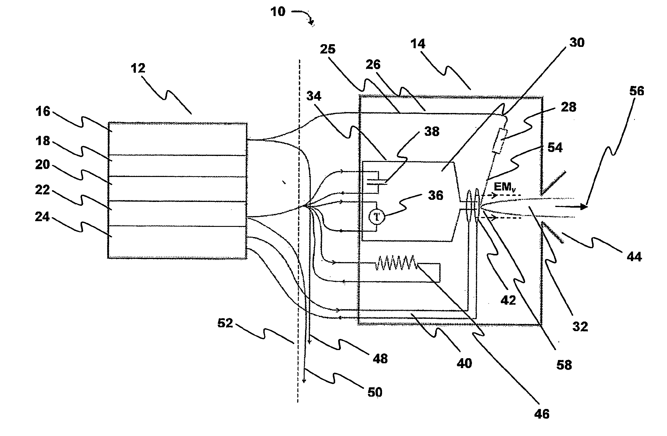
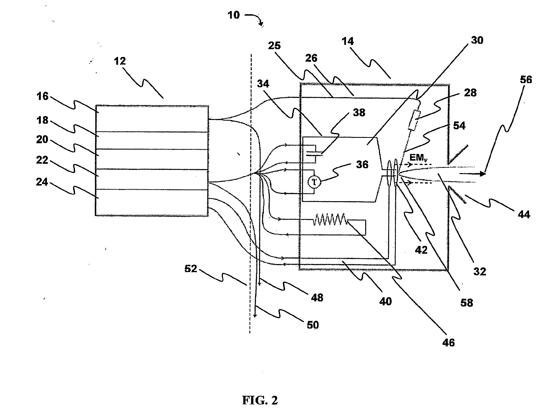
[0043]FIG. 2 shows one hybrid-electric laser propulsion (HELP) thruster 10, illustrating certain block functional components of thruster 10 used in thruster operation such as described below. In particular, HELP thruster 10 provides four principle functions: laser ablation, plasma collimation, propellant feed, and control & power conversion; in one embodiment, these functions are implemented by two units: an electronics & control unit 12 and a replaceable modular propellant pod 14.

[0044] Unit 12 is shown with a low power, diode pumped solid-state laser array 16, a power converter 18, a micro-controller 20, a propellant control board 22, and an electromagnetic (EM) pulse generator 24. These components of unit 12 enable control of components of unit 14, such as: laser control, closed-loop heater control and control of an electromagnetic field 58.

[0045] Laser-light 25 from laser array 16 is carried to a Q-switched microchip laser 28 (see FIG. 3) of unit 14 through fiber optics 26; th...


PUM


Abstract

A hybrid electric-laser propulsion (HELP) thruster. A propellant has self-regenerative surface morphology. A laser ablates the propellant to create an ionized exhaust plasma that is non-interfering with a trajectory path of expelled ions. An electromagnetic field generator generates an electromagnetic field that defines a thrust vector for the exhaust plasma. Multiple HELP thrusters may be ganged together, and controlled, according to mission criteria.

Description

RELATED APPLICATION [0001] This is a nonprovisional. application of U.S. Letters Patent Ser. No. 60 / 482,601 entitled HYBRID ELECTRIC-LASER PROPULSION SYSTEM AND ASSOCIATED METHODS the aforementioned application is incorporated herein by reference thereto.BACKGROUND [0002] The increasing demand in science and military applications for precision orbital positioning and formation flying platforms has created a need for enabling thruster technologies. [0003] Electric and laser-type thrusters are micro-propulsion technologies that convert electric / laser energy into exhaust kinetic energy, to generate a force (“thrust”). Various forms of electric-type thrusters (e.g., Pulsed Plasma Thrusters (PPT), Hall thrusters, Field Emission Electric Propulsion (FEEP) and Colloid thrusters) have been researched since the early 1950's, while laser-type thrusters for use in space applications has been researched since the early 1970's. Major limiting factors in these thrusters include poor repeatability...

Claims


Application Information

Patent Timeline
Patent Type & Authority Applications(United States)
IPC IPC(8): B64G1/40F02K9/68F03H1/00
CPCB64G1/405F03H1/0081F03H1/0012B64G1/413
Inventor LEACH, RACHELMURPHY, GERALD BERNARDADAMS, THOMAS SETON
Owner DESIGN NET ENG
Learn More